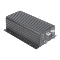
Curtis PMC 1204/1205 Manual
v
FIGURES
FIG. 1 Curtis PMC 1205 electronic motor controller............... 1
FIG. 2 Mounting dimensions,
Curtis PMC 1204/1205 controller ................................ 3
FIG. 3 Mounting dimensions,
Curtis PMC potboxes PB-5, -6, -9, and -10 .................. 5
FIG. 4 Curtis PMC footpedal FP-2 .......................................... 5
FIG. 5 Typical installation,
Curtis PMC 1204/1205 controller ................................ 6
FIG. 6 Basic wiring for use with series motors .......................... 10
FIG. 7 Alternate control wiring, to provide freewheeling .......... 11
FIG. 8 Alternate power wiring, for reversing with
4×SPST contactors ........................................................ 12
FIG. 9 Alternate power wiring, for reversing with
mechanical forward/reverse switch arm .......................... 13
FIG. 10 Standard throttle pot, 0–5kΩ ........................................ 14
FIG. 11 Bi-directional twist-grip throttle with
10 kΩ center-tapped, 4-terminal pot ............................. 14
FIG. 12 Bi-directional twist-grip throttle with
20 kΩ pot and controller with optional
5kΩ–0 throttle input ..................................................... 15
FIG. 13 Reduced speed operation (with standard 0–5kΩ pot) .... 15
FIG. 14 Curtis PMC electronic throttle (ET series) .................... 16
FIG. 15 Basic wiring for use with
permanent magnet (PM) motors ................................... 17
FIGURES

 Loading...