User Guide DDOC0199-000-A9
1-Slot Data Transport System (CSfC) 4 - 3 Controls and Indicators
© 2024 Curtiss-Wright Defense Solutions Revision 1.0
4.3 RMC Module Controls / Indications
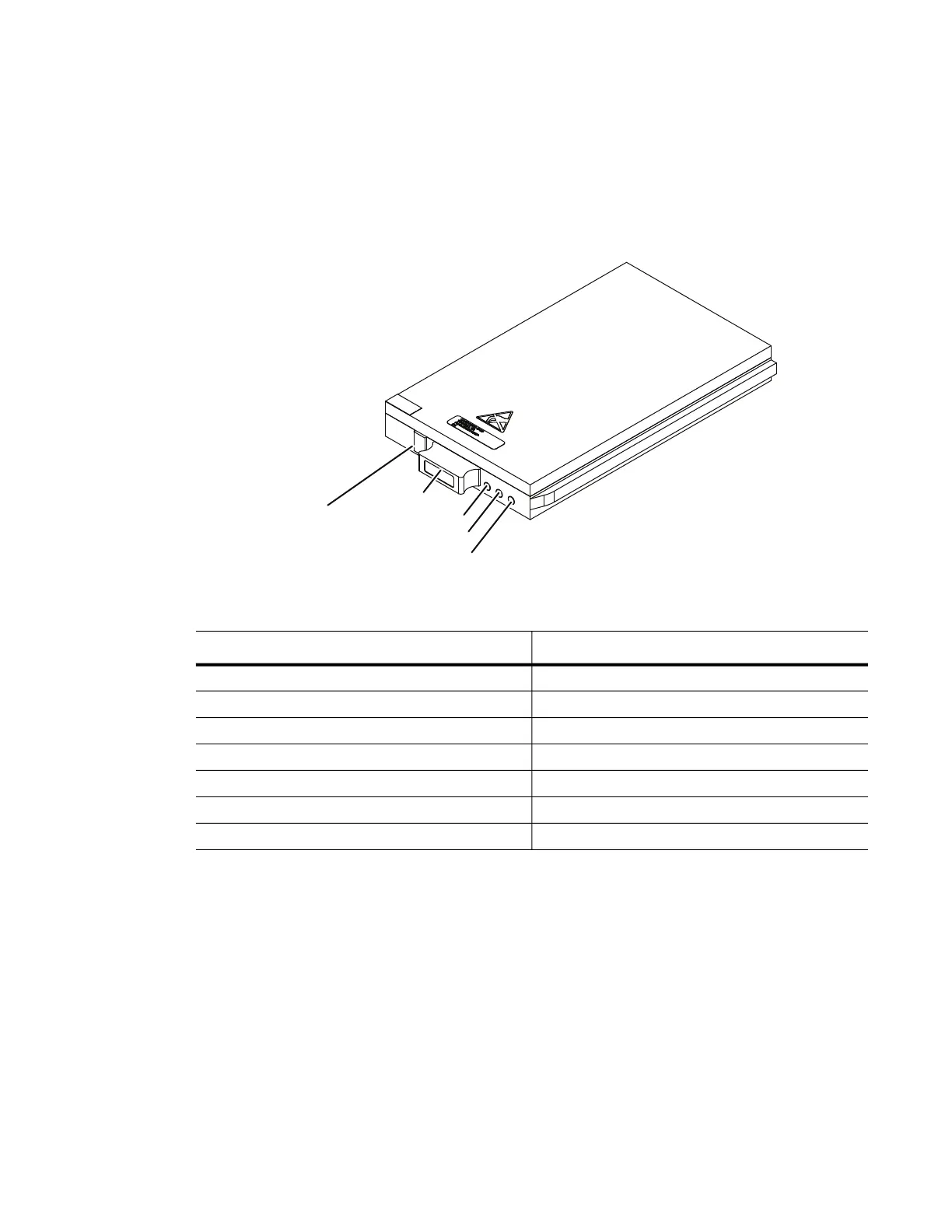
The RMC module (located behind the DTS1+ CSfC storage bay door) has its own controls /
indicators as shown in Figure 4.4. The function of these controls and indicators is as follows.
4.3.1 STATUS LED (Green / Left)
When this green (left) LED is illuminated it indicates that the RMC module is functioning properly. If
there is a change in status or a problem, this LED will indicate the nature of the condition by the
behavior outlined in Table 4.1.
Figure 4.4 RMC Module Controls / Indicators
4.3.2 ACTIVITY LED (Green / Middle)
This green (middle) LED is an indicator of SATA disk activity. This function is not supported on all
configurations.
4.3.3 FAULT LED
This red LED indicates the BIT has failed or an operational anomaly was detected such as power
levels, data connections, or optional security functions. This LED will be ON during initialization
and then remain OFF during normal operation. See the Troubleshooting section for actions to
take if the RMC module FAULT LED is illuminated.
Table 4.1 RMC Module STATUS LED Indications
LED Behavior Meaning
Steady On
RMC
module detected, mounted, and ready
Steady Off
RMC
module not detected
Slow blinking (1Hz)
RMC
module detected, not mounted
Fast blinking (5Hz) for 2 seconds Button-hold acknowledge*
1 blink, 4 seconds off Ready for removal*
2 blink, 3 seconds off Auto-mount failure
5 blink, 3 seconds off
RMC
module monitoring error
DDOC0199-0004
FAULT LED
ACTIVITY LED
STATUS LED
HANDLE
REMOVAL
REQUEST
BUTTON