16
GETTING TO KNOW YOUR IPC-R1ix
.rotcennoc 54-JR nip-8 esu 2 dna 1 strop NAL tenrehtE spbM 0001/001/01 ehT
LAN1 is equipped with Intel 82579LM for AMT function. LAN2 is equipped with
Intel 82574L.
Using suitable RJ-45 cable, you can connect IPC-R1ix system to a
computer, or to any other piece of equipment that has an Ethernet connection,
for example, a hub or a switch.
Moreover, both of them have Wake-on-LAN and Pre-boot Execution
Environment capabilities. The following diagram shows the pinouts for LAN1
and LAN2 port.
Pin No. 10 / 100 Mbps 1000 Mbps
1 E_TX+ MDI0_P
2 E_TX- MDI0_N
3 E_RX+ MDI1_P
4 ---- MDI2_P
5 ----- MDI2_N
6 E_RX- MDI1_N
7 ----- MDI3_P
8 ------ MDI3_N
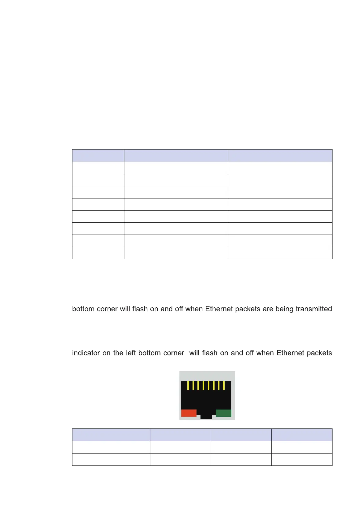
The Ethernet ports use standard RJ-45 jack connectors with LED indicators on
the front side to show Active/Link status and Speed status. The LED indicators
on the right bottom corners glow a solid green color when the cable is properly
connected to a 100 Mbps Ethernet network. The LED indicator on the left
or received.
The LED indicators on the right bottom corners glow a solid orange color when
the cable is properly connected to a 1000 Mbps Ethernet network. The LED
are being transmitted or received.
Location 10 Mbps 100 Mbps 1000 Mbps
Right Bottom LED off Solid Green Solid Orange
Left Bottom LED Flash Yellow Flash Yellow Flash Yellow
1 8