35
GETTING TO KNOW YOUR IPC-R1ix
Both mSATA and Mini PCIe share the same form-factor and similar electrical
pin-out assignments on their connectors. There was no clear mechanism to
distinguish if a mSATA drive or a Mini PCIe device is plugged into the socket
43 on mSATA connector as “no connect” instead of “return current path” ( or
GND).
When an mSATA drive is inserted, its pin 43 is “no connect”, and the respective
pin on the socket is being pulled-up to logic 1. When a Mini PCIe device is
inserted, its pin 43 forces the respective pin on the socket to ground, or logic 0.
IPC-R1ix using Pin 43 status designed for switching between mSATA
drive and Mini PCIe device.
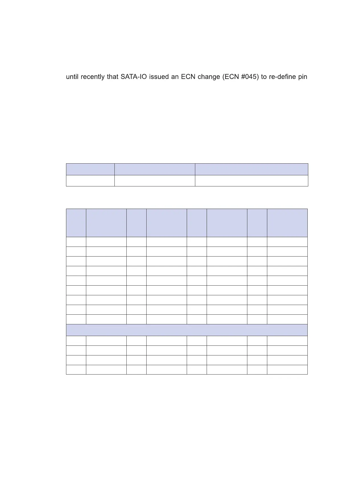
Status Mini PCIe card mSATA drive
Pin 43 Logic 0 Logic 1
CN12 Mini PCIe Connector Pin-Out
Pin
No.
Signal
Name
Pin
No.
Signal
Name
Pin
No.
Signal
Name
Pin
No.
Signal
Name
51 Reserved 52 +3.3Vaux 33 PETp0 34 GND
49 Reserved 50 GND 31 PETn0 32 SMB_DATA
47 Reserved 48 +1.5V 29 GND 30 SMB_CLK
45 Reserved 46 Reserved 27 GND 28 +1.5V
43 Status 44 Reserved 25 PERp0 26 GND
41 +3.3Vaux 42 Reserved 23 PERn0 24 +3.3Vaux
39 +3.3Vaux 40 GND 21 GND 22 PERST#
37 GND 38 USB_D+ 19 Reserved 20 reserved
35 GND 36 USB_D- 17 Reserved 18 GND
Mechanical Key
15 GND 16 Reserved 7 CLKREQ# 8 Reserved
13 REFCLK+ 14 Reserved 5 Reserved 6 1.5V
11 REFCLK- 12 Reserved 3 Reserved 4 GND
9 GND 10 Reserved 1 WAKE# 2 3.3Vaux