Cybex Pro+ Treadmill Service Manual
Service
Page 4-14
14. Secure the front roller.
Slide the front roller into the running belt. A. NOTE: It doesn’t matter
which way the running belt goes.
Be sure the drive belt is around the fl ywheel pulley and the front B.
roller before attaching the front roller.
Using a 9/16” socket wrench with a 3” extension, attach the two C.
screws that fasten the front roller to the frame. NOTE: Tighten
each of the two screws evenly, making sure not to tighten one
screw too many turns before moving to the other screw.
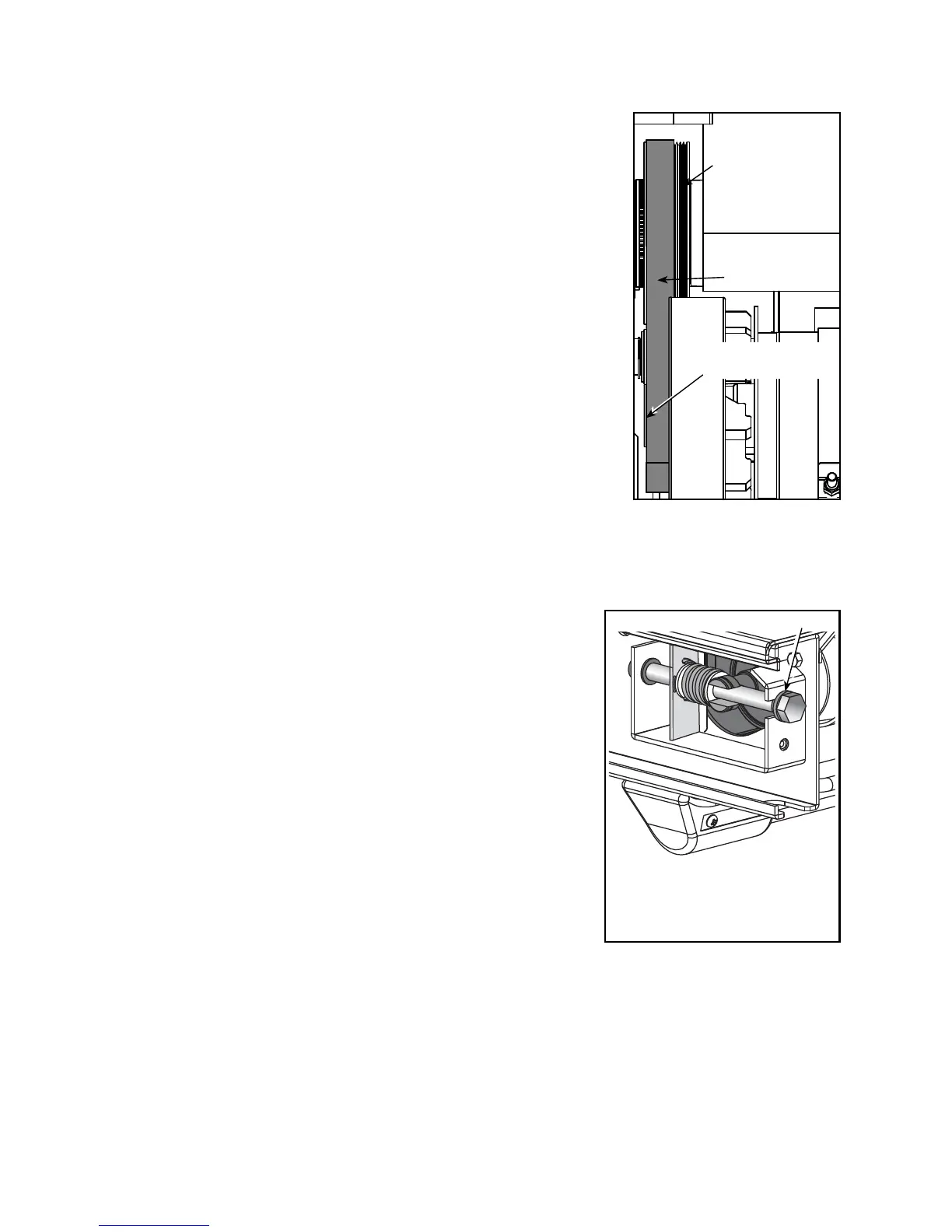
Confi rm that the drive belt fi lls all grooves in the drive motor D.
fl ywheel pulley and there are open grooves on the inside of the front
roller. See Figure 11. NOTE: Failure to align the drive belt could
cause squeaking.
15. Secure the drive belt tension.
NOTE: Follow this step only if you replaced the drive belt.
Using a 1/2” socket wrench, tighten the two screws on the A.
motor saddle. See Figure 10.
16. Secure the running deck.
Place the deck in position as noted in step 11A. A. NOTE: Make a note of the service you performed
on the Service Schedule under the motor cover.
Using a 7/16” open end or socket wrench, attach the ten B.
washers and screws that hold the deck to the treadmill frame.
See Figure 7.
17. Secure the rear roller.
Slide the rear roller into the running belt. See Figure 6.A.
Slide the hardware for each side into position. B. NOTE: Place the
end of the bolt in fi rst and then hold the rear roller up while you
pivot the group of hardware into the rear roller slot. Be sure the
bronze bushing is touching the head of the bolt. See Figure 12.
Using a 3/4” socket wrench, tighten each rear roller bolt C.
evenly, making sure not to tighten either bolt too many turns
before moving to the other bolt. NOTE: Do not overtighten
the belt. You will tension and center the belt in step 22. See
Figure 12.
18. Secure the top steps.
Place each top step in position. See Figure 5.A.
Using a Phillips screwdriver, secure the three screws that hold each top step in place. See B.
Figure 5.
19. Secure the side panels.
Place each side panel into position on the bottom edge and use your hand to push all along the A.
top edge of the side panel to snap it in place. See Figure 5.
Bronze Bushing
Figure 12
Figure 11
Open grooves
on Front Roller
Drive Motor
Flywheel Pulley
NOTE: Be sure the bronze
bushing is touching the head
of the bolt.
Drive Belt