Delivery
& Installation
Page 5-4
Cybex VR2 Owner’s Manual
H. Wipe guide rods clean over entire length.
Lubricate with light coating of medium
weight automotive engine oil.
I. With an assistant present, carefully install
each weight plate one at a time.
NOTE: For all machines except the Hip
Abduction, HIp Adduction and Rotary
Calf, lean guide rods toward weight
stack guards when installing weight
plates. For the Hip Abduction, Hip
Adduction and Rotary Calf machines,
lean guide rods away from the weight
stack guard (toward the operator
position).
J. Carefully slide top weight onto guide rods.
NOTE: Position top weight so that the tab is
nearest the increment rod on the frame.
See Figure 3 for location of tab.
K. On one of the guide rods, place lower snap
ring and wave washer (removed in step 5)
and wave washer at least two inches below
top end of guide rod.
L. Raise guide rod up through mounting hole
and install the upper snap ring into the top
groove.
M.Lower guide rod and secure lower snap ring
into the groove. Repeat steps 6K - 6M for
the other guide rod.
NOTE: Be sure wave washer is between frame
and lower snap ring. See Figures 1
and 2.
N. Place protective caps over the weight stack
guide rod holes.
O. Place top weight increment rod onto the top
weight and secure using two nylon locknuts
and two SHCS .375-16 x 1.25. See Figure 3.
3.Belt Routing.
A. Carefully lift top weight and verify that the
top weight belt clamp is parallel with the
pulley bracket.
B. Verify that the SHCS securing belt clamp
faces weight stack guard. See Figure 4.
Figure 4
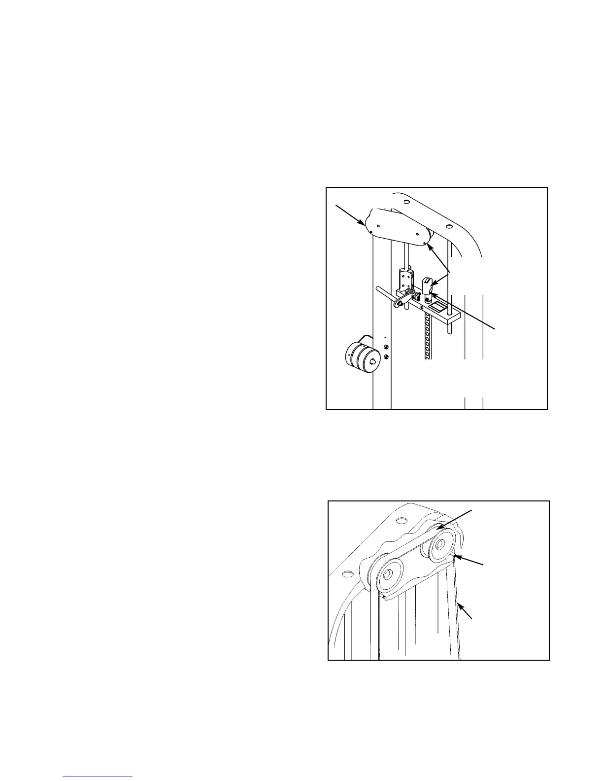
C. Route belt through top pulley bracket,
making sure that the belt is routed on the
outside of each pin as shown in Figure 5.
Figure 5
Belt should not
ride up on
pulley flange
Pin
Belt
Route belt on
outside of each
pin
NOTE: Belt clamp
must be parallel
with pulley bracket.
Pulley Bracket
Belt
Clamp
NOTE: Weight
selector pin is not
shown.