CY7C68013
Document #: 38-08012 Rev. *A Page 14 of 48
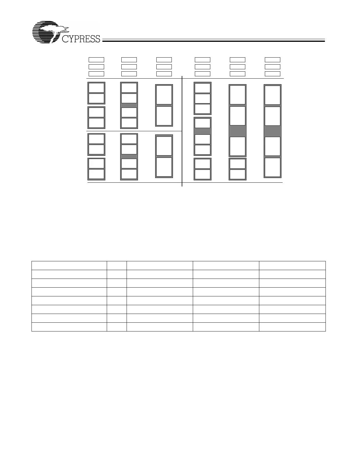
3.11.4 Endpoint Configurations (High-speed Mode)
Endpoints 0 and 1 are the same for every configuration. Endpoint 0 is the only CONTROL endpoint, and endpoint 1 can be either
BULK or INTERRUPT. To the left of the vertical line, the user may pick different configurations for EP2&4 and EP6&8, since none
of the 512-byte buffers are combined between these endpoint groups. An example endpoint configuration would be:
EP2—1024 double buffered; EP6—512 quad buffered.
To the right of the vertical line, buffers are shared between EP2–8, and therefore only entire columns may be chosen.
3.11.5 Default Full-Speed Alternate Settings
Notes:
1. “0” means “not implemented.”
2. “2x” means “double buffered.”
Table 3-4. Default Full-Speed Alternate Settings
[1, 2]
Alternate Setting 0 1 2 3
ep0 64 64 64 64
ep1out 0 64 bulk 64 int 64 int
ep1in 0 64 bulk 64 int 64 int
ep2 0 64 bulk out (2×) 64 int out (2×) 64 iso out (2×)
ep4 0 64 bulk out (2×) 64 bulk out (2×) 64 bulk out (2×)
ep6 0 64 bulk in (2×) 64 int in (2×)64 iso in (2×)
ep8 0 64 bulk in (2×) 64 bulk in (2×) 64 bulk in (2×)
64
64
64
64
64
64
64
64
64
64
64
64
64
64
64
64
64
64
512
512
512
512
512
512
512
512
512
512
512
512
512
512
512
512
1024
1024
1024
1024
1024
1024
1024
1024
1024
1024
1024
512
512
512
512
512
512
512
512
512
512
EP2
EP2 EP2
EP2
EP2
EP2
EP4
EP6
EP8
EP6 EP6
EP6
EP8 EP8
EP0 IN&OUT
EP1 IN
EP1 OUT
Figure 3-3. Endpoint Configuration