CY7C68013
Document #: 38-08012 Rev. *A Page 25 of 48
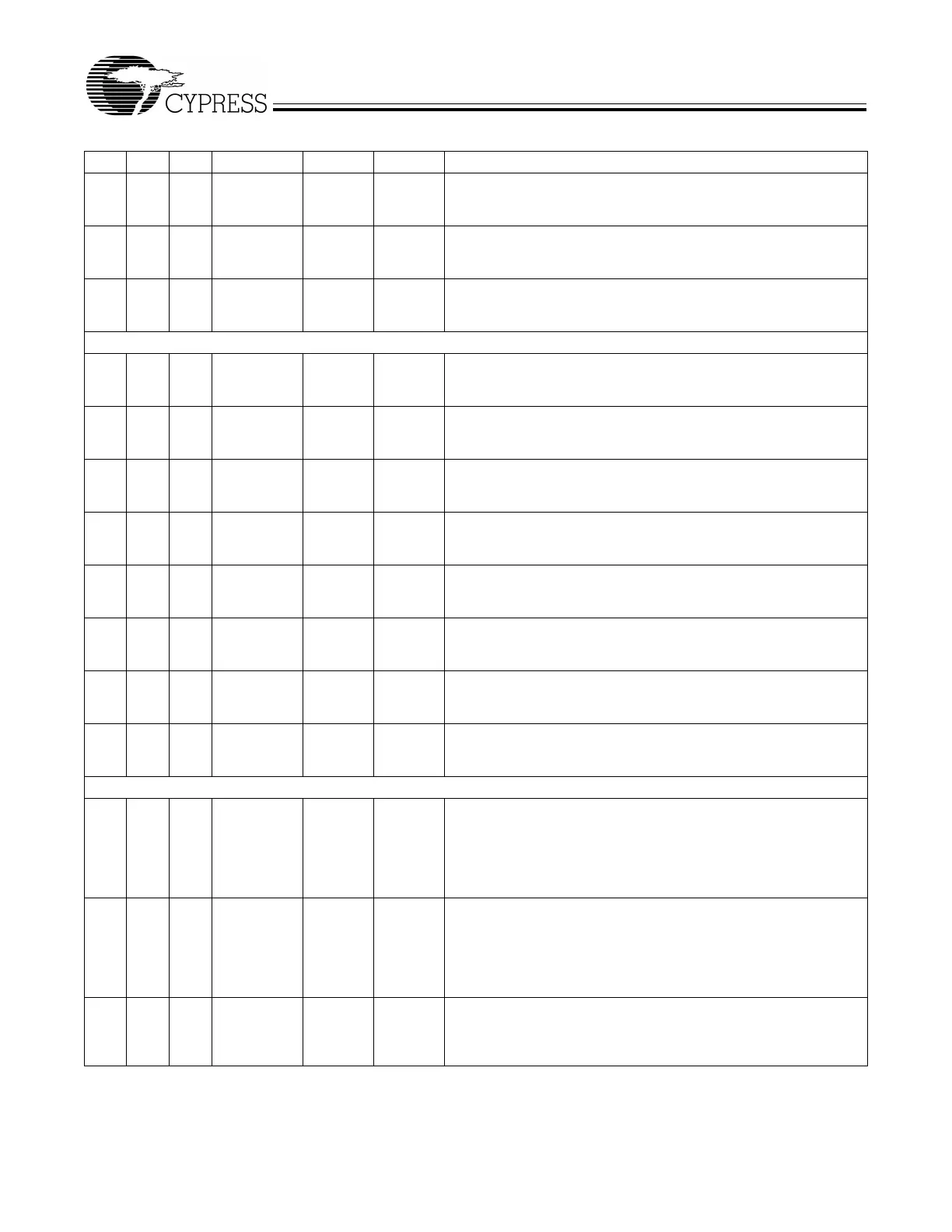
77 62 PC5 or
GPIFADR5
I/O/Z I
(PC5)
Multiplexed pin whose function is selected by PORTCCFG.5
PC5 is a bidirectional I/O port pin.
GPIFADR5 is a GPIF address output pin.
78 63 PC6 or
GPIFADR6
I/O/Z I
(PC6)
Multiplexed pin whose function is selected by PORTCCFG.6
PC6 is a bidirectional I/O port pin.
GPIFADR6 is a GPIF address output pin.
79 64 PC7 or
GPIFADR7
I/O/Z I
(PC7)
Multiplexed pin whose function is selected by PORTCCFG.7
PC7 is a bidirectional I/O port pin.
GPIFADR7 is a GPIF address output pin.
PORT D
102 80 52 PD0 or
FD[8]
I/O/Z I
(PD0)
Multiplexed pin whose function is selected by the IFCONFIG[1..0]
and EPxFIFCFG.0 (wordwide) bits.
FD[8] is the bidirectional FIFO/GPIF data bus.
103 81 53 PD1 or
FD[9]
I/O/Z I
(PD1)
Multiplexed pin whose function is selected by the IFCONFIG[1..0]
and EPxFIFCFG.0 (wordwide) bits.
FD[9] is the bidirectional FIFO/GPIF data bus.
104 82 54 PD2 or
FD[10]
I/O/Z I
(PD2)
Multiplexed pin whose function is selected by the IFCONFIG[1..0]
and EPxFIFCFG.0 (wordwide) bits.
FD[10] is the bidirectional FIFO/GPIF data bus.
105 83 55 PD3 or
FD[11]
I/O/Z I
(PD3)
Multiplexed pin whose function is selected by the IFCONFIG[1..0]
and EPxFIFCFG.0 (wordwide) bits.
FD[11] is the bidirectional FIFO/GPIF data bus.
121 95 56 PD4 or
FD[12]
I/O/Z I
(PD4)
Multiplexed pin whose function is selected by the IFCONFIG[1..0]
and EPxFIFCFG.0 (wordwide) bits.
FD[12] is the bidirectional FIFO/GPIF data bus.
122 96 1 PD5 or
FD[13]
I/O/Z I
(PD5)
Multiplexed pin whose function is selected by the IFCONFIG[1..0]
and EPxFIFCFG.0 (wordwide) bits.
FD[13] is the bidirectional FIFO/GPIF data bus.
123 97 2 PD6 or
FD[14]
I/O/Z I
(PD6)
Multiplexed pin whose function is selected by the IFCONFIG[1..0]
and EPxFIFCFG.0 (wordwide) bits.
FD[14] is the bidirectional FIFO/GPIF data bus.
124 98 3 PD7 or
FD[15]
I/O/Z I
(PD7)
Multiplexed pin whose function is selected by the IFCONFIG[1..0]
and EPxFIFCFG.0 (wordwide) bits.
FD[15] is the bidirectional FIFO/GPIF data bus.
Port E
108 86 PE0 or
T0OUT
I/O/Z I
(PE0)
Multiplexed pin whose function is selected by the PORTECFG.0 bit.
PE0 is a bidirectional I/O port pin.
T0OUT is an active-HIGH signal from 8051 Timer-counter0. T0OUT
outputs a high level for one CLKOUT clock cycle when Timer0 over-
flows. If Timer0 is operated in Mode 3 (two separate timer/counters),
T0OUT is active when the low byte timer/counter overflows.
109 87 PE1 or
T1OUT
I/O/Z I
(PE1)
Multiplexed pin whose function is selected by the PORTECFG.1 bit.
PE1 is a bidirectional I/O port pin.
T1OUT is an active-HIGH signal from 8051 Timer-counter1. T1OUT
outputs a high level for one CLKOUT clock cycle when Timer1 over-
flows. If Timer1 is operated in Mode 3 (two separate timer/counters),
T1OUT is active when the low byte timer/counter overflows.
110 88 PE2 or
T2OUT
I/O/Z I
(PE2)
Multiplexed pin whose function is selected by the PORTECFG.2 bit.
PE2 is a bidirectional I/O port pin.
T2OUT is the active-HIGH output signal from 8051 Timer2. T2OUT
is active (HIGH) for one clock cycle when Timer/Counter 2 overflows.
Table 4-1. FX2 Pin Descriptions
[5]
(continued)
128 100 56 Name Type Default Description
 Loading...


