DGS-3630 Series Layer 3 Stackable Managed Switch Hardware Installation Guide
28
used to connect devices to the Switch over great distances. The maximum distance that the RJ45 wiring connection
can reach is 100 meters. Fiber optic connections can span several kilometers.
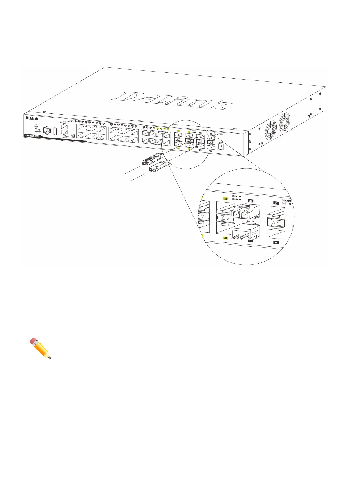
The figure below illustrates how to properly insert SFP+ transceivers into the Switch’s SFP+ ports.
Figure 3-4 Inserting transceivers into the transceiver ports
The SFP+ ports also support other transceiver form factors like SFP and SFP+ transceivers. A complete list of
SFP/SFP+ transceivers, compatible with this switch, can be found the SFP Ports and SFP+ Ports sections in
Appendix A - Technical Specifications at the end of this document.
NOTE: Only use pluggable optical modules and Direct-Attach Cables (DAC) that meet the following
regulatory requirements:
Class 1 Laser Product
UL and/or CSA registered component for North America
FCC 21 CFR Chapter 1, Sub-chapter J in accordance with FDA & CDRH requirements
IEC/EN 60825-1/-2: 2007 2nd edition or later, European Standard
Power On (AC Power)
Plug one end of the AC power cord into the power socket of the Switch and the other end into the local power source
outlet. After the system is powered on, the LED will blink green to indicate that the system is booting up.
 Loading...