DGS-3630 Series Layer 3 Stackable Managed Switch Hardware Installation Guide
17
For a complete list of SFP/SFP+ transceivers that are compatible with this switch, refer to the SFP Ports and SFP+
Ports sections in Appendix A - Technical Specifications.
LED Indicators
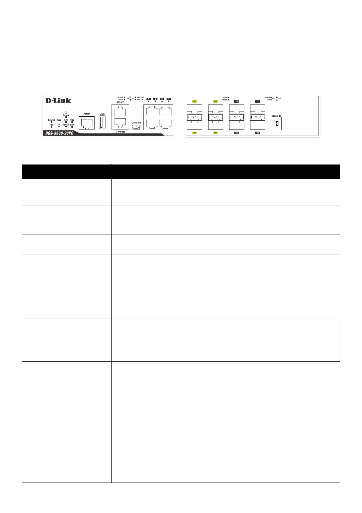
Located on the front panel of this switch are LED indicators: Power, Console, RPS, Fan Err, USB, MGMT, Link/Act
and PoE indicators for all the ports, Link/Act and PoE indicators for mode selection, and Stack ID.
Figure 2-10 LED indicators for the DGS-3630-28PC
This LED will light solid green after the Switch has been powered on successfully.
This LED will be off when the Switch is no longer receiving power (i.e. powered
off).
This LED will light solid green when the RJ45 console port is active.
The LED will light solid amber when the mini-USB console port is active.
This LED will be off when both console ports are not active.
This LED will light green when the Redundant Powers Supply is in use.
This LED will be off when the RPS is not in use.
This LED will light solid red when the fan fails.
This LED will be off when the fan is operating normally.
This LED will light solid green if a USB flash drive is plugged in.
This LED will blink green when the Switch is reading or writing data to and from
the USB drive.
This LED will be off when no USB drive is plugged into the USB port.
This LED will light solid red when a USB drive failure has been detected.
This LED will light solid green after a link to the MGMT port was successfully
established.
This LED will blink when activity on this port is taking place.
This LED will be off when there is no link present or when this interface was shut
down from within the Switch’s configuration.
The Switch has LED indicators for Link and Activity.
RJ45 Ports: This LED will light solid green when there is a connection (or link) to
a 1000 Mbps Ethernet device or solid amber when there is a connection (or link)
to a 10/100 Mbps Ethernet device on any of the RJ45 ports. The LED will blink
green when a 1000 Mbps port is active or blink amber when a 10/100 Mbps port is
active. The LED will be off when there is no link or activity.
SFP Ports: This LED will light solid green when there is a connection (or link) to a
1000 Mbps Ethernet device or solid amber when there is a connection (or link) to
a 100 Mbps Ethernet device on any of the SFP ports. The LED will blink green
when a 1000 Mbps port is active or blink amber when a 100 Mbps port is active.
The LED will be off when there is no link or activity.
SFP+ Ports: This LED will light solid green when there is a connection (or link) to
a 10 Gbps Ethernet device or solid amber when there is a connection (or link) to a
1 Gbps Ethernet device at any at any of the SFP+ ports. The LED will blink green
when a 10 Gbps port is active or blink amber when a 1 Gbps port is active. The
LED will be off when there is no link or activity.
 Loading...