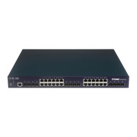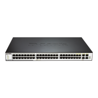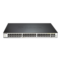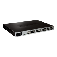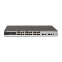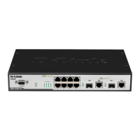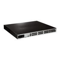
Do you have a question about the D-Link DGS-3627G - xStack Switch - Stackable and is the answer not in the manual?
| Enclosure Type | Rack-mountable |
|---|---|
| Switching Capacity | 128 Gbps |
| Forwarding Rate | 95.2 Mpps |
| MAC Address Table Size | 16K entries |
| Power Device | Internal power supply |
| Voltage Required | AC 120/230 V (50/60 Hz) |
| Device Type | Switch |
| Routing Protocol | RIP-1, RIP-2, static IP routing |
| Remote Management Protocol | SNMP 1, SNMP 2, SNMP 3, Telnet, HTTP, HTTPS, CLI |
| Features | Flow control, DHCP support, BOOTP support, ARP support, VLAN support, IGMP snooping, port mirroring, DiffServ support, IPv6 support, Quality of Service (QoS) |
| Compliant Standards | IEEE 802.3, IEEE 802.3u, IEEE 802.3ab, IEEE 802.3z, IEEE 802.1D, IEEE 802.1Q, IEEE 802.3x, IEEE 802.1p, IEEE 802.1w, IEEE 802.1s, IEEE 802.1X, IEEE 802.3ad |
| VLAN Support | Yes |
| Quality of Service (QoS) | Yes |
| Security Features | RADIUS, SSH |
| Management | Web-based management |
Provides an overview of the Web UI Reference Guide and its purpose for network managers.
Step-by-step guide to accessing the switch's management interface via a web browser.
Lists and describes the main folders and windows available in the web interface.
Displays key settings, firmware version, hardware version, and serial number for the switch.
Configures the switch's IP address, subnet mask, and default gateway for network management.
Details the xStack® DGS-3600 Series stacking feature, topologies, and switch roles.
Configures various attributes and properties for individual physical ports, including speed and flow control.
Manages user privileges, allowing creation, modification, and deletion of accounts.
Configures the logging of events, including sending messages to Syslog servers and save modes.
Configures time settings for the switch, including SNTP server and Time Zone/DST.
Manages file transfers for firmware upgrades, configuration files, and log files via TFTP.
Provides access to the switch's flash memory for managing firmware and configuration files.
Configures the relay function for DHCP/BOOTP information between clients and servers.
Configures SNMP settings for network management, including versions, community strings, and traps.
Manages multiple switches under a single IP address, simplifying network administration.
Configures Virtual Local Area Networks for network segmentation and management.
Optimizes multicast traffic by allowing the switch to recognize IGMP queries and reports.
Configures Spanning Tree Protocol (STP, RSTP, MSTP) to prevent network loops and ensure fault tolerance.
Configures Link Layer Discovery Protocol for advertising network connectivity and management information.
Configures IP interfaces, including IPv4, IPv6, and loopback interfaces.
Configures the Open Shortest Path First routing protocol for dynamic network path determination.
Configures the switch to act as a DHCP server for automatic IP address assignment to network devices.
Configures Border Gateway Protocol (BGP) for inter-autonomous system routing and policy enforcement.
Configures priority queuing for Quality of Service, mapping traffic to hardware queues based on priority.
Places a ceiling on transmitting and receiving data rates for selected ports to manage bandwidth.
Defines specific time periods for enabling Access Profile rules, enhancing security policy management.
Establishes criteria (MAC, IP, Packet Content) to determine whether the switch forwards packets.
Configures IP packet flow metering and marking based on color codes (green, yellow, red).
Creates access rules for packets destined for the switch's CPU interface to enhance security.
Prevents unauthorized MAC addresses from connecting to switch ports by locking learned MAC addresses.
Restricts client access by binding MAC and IP addresses to specific switch ports, enhancing network security.
Implements port-based and MAC-based access control for network device authentication via RADIUS.
Configures a list of MAC addresses for authentication, mapping them to target VLANs for access rights.
Protects the switch CPU from packet flooding attacks by metering and limiting traffic flows.
Enables secure remote login and network services over an insecure network using encrypted communication.
Displays status information for internal power, external power, fans, and CPU utilization.
Shows all switches in the stack and their configuration information, including topology and roles.
Displays the percentage of CPU usage calculated as a simple average by time interval.
Displays the percentage of total available bandwidth being used on each port.
Displays port error statistics compiled by the switch management agent, shown as line graphs or tables.
Shows the current IP routing table of the switch, allowing search for specific IP routes.
Allows viewing the switch's history log, compiled by the management agent, categorized by type and severity.
Provides options for resetting the switch, retaining some configurations or restoring factory defaults.
Restarts the switch, potentially losing unsaved configuration changes.
Saves configurations to the switch's memory (RAM and NV-RAM) for permanent retention.
Lists supported protocols, fiber-optic standards, and network cable specifications.
Explains the procedure for physically accessing the device via console port to reset passwords.
Configures ingress/egress bandwidth assignment via RADIUS Server for ports.


