Configuring the WLAN and Tunnel Interfaces 219
L3 Roaming Example
3. Exit to Privileged EXEC mode and view the VLAN routing interface configuration.
(switch-prompt) (Vlan)#exit
(switch-prompt) #show ip vlan
MAC Address used by Routing VLANs: 00:00:00:01:00:02
Logical
VLAN ID Interface IP Address Subnet Mask
------- -------------- --------------- ---------------
200 0/4/1 0.0.0.0 0.0.0.0
The new VLAN routing interface is 0/4/1 in unit/slot/port format. For non-stacking
platforms, the interface would be 4/1.
4. Enter the interface configuration mode for the new VLAN routing interface.
(switch-prompt) #configure
(switch-prompt) (Config)#interface 0/4/1
5. Assign an IP address to the interface and enable routing.
(switch-prompt) (Interface 0/4/1)#ip address 192.168.60.15 255.255.255.0
(switch-prompt) (Interface 0/4/1)#routing
6. Add the port to which the call server is attached to VLAN 200 (in this example, the call
server is attached to port 3).
(switch-prompt) (Config)#interface 1/0/3
(switch-prompt) (Interface 1/0/3)#vlan participation include 200
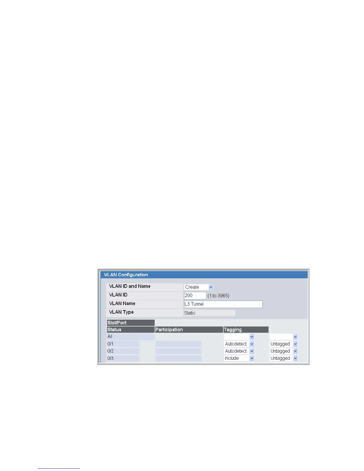
To perform the same steps by using the Web interface, use the following procedures:
1. From the L2 Features > VLAN > Configuration page, create a VLAN, give it a name,
and add the port to which the call server is attached to VLAN 200 (in this example, the call
server is attached to port 3).