ENGLISH
42
8.1
CHARACTERISTICS AND INTERPRETATIONS
Ref. FUNCTION
L – N
SINGLE-PHASE
R – S – T
THREE-PHASE
Power supply line connection terminals.
Line earth system connection terminal.
U - V – W
THREE-PHASE
R – S
SINGLE-PHASE
Three-phase pump connection terminals.
Pump earth system connection terminal.
J22
1
Power supply terminal: + 12V DC – 50Am.
(excluding A.D. M/M 1.1 and A.D. M/T 1.0)
2=IN 3
Connection terminal of input i3 for general disabling command.
(excluding A.D. M/M 1.1 and A.D. M/T 1.0)
3=IN 2
Connection terminal of input i2 for selecting set point 1.
(excluding A.D. M/M 1.1 and A.D. M/T 1.0)
4
Common connection terminal I3 – I2
(excluding A.D. M/M 1.1 and A.D. M/T 1.0)
6=IN 1
Connection terminals of input i1 for protection against dry running.
(excluding A.D. M/M 1.1 and A.D. M/T 1.0)
7
Connection terminal: 0V DC (GND).
(excluding A.D. M/M 1.1 and A.D. M/T 1.0)
J14
o1
Remote alarm connection terminal. (excluding A.D. M/M 1.1 and A.D. M/T 1.0)
250 Vac – 6 A max resistive load – 3 A max inductive load
o2
Pump operating connection terminal. (excluding A.D. M/M 1.1 and A.D. M/T 1.0)
250 Vac – 6 A max resistive load – 3 A max inductive load
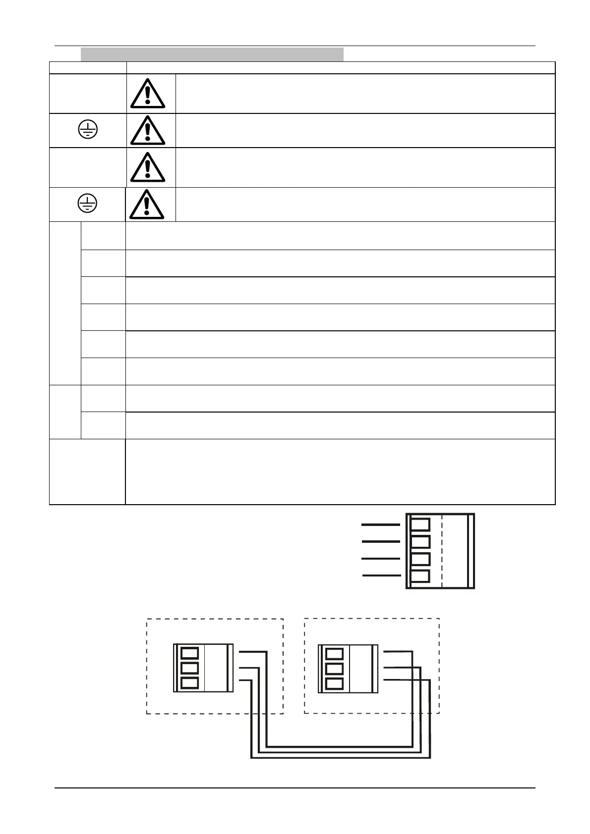
J9
Connection terminals for interconnection and exchange.
ATTENTION: For interconnection cables with a length of more than 1 m, it is
recommended to use screened cable with the braiding connected to earth (central pin
number 2) on both appliances. ATTENTION: Scrupulously respect the connection
sequence between the two appliances! (excluding A.D. M/M 1.1) (see fig.2)
Fig. 1
Fig. 2
For functionality and programming:
see table on page 49 “Assigning the parameters that associate functions with the digital outputs OUT1, OUT2”
3
2
1
3
2
1
J 9
J 9
Primary
Active Driver
Secondary
Active Driver
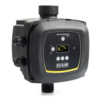
ACTIVE DRIVER M/T 2.2
o2
o1
J 14
1
4
2
3
 Loading...