- 81 -
14. SPECIFICATIONS (continued)
٨Initial Values and Setting Range of Parameters
Initial value Setting range
Pre flow time 0.3 sec. 0 – 20 sec.
Up slope time 1 sec. 0 – 10 sec.
Welding current for stick welding 10 A
10 – 250 A
䊶 Initial current
䊶 Welding current
䊶 Pulse current
䊶 Crater current
DC TIG
10 A
4 – 300 A
AC TIG
AC-DC 䌔䌉䌇
STANDARD
HARD
10 - 300 A
SOFT 10 – 200 A
Pulse frequency 2 Hz 0.1 – 500 Hz
Down slope time 1 sec. 0 – 10 sec.
Post flow time 7 sec. 0 – 30 sec.
Arc spot time 3 sec. 0.1 – 10 sec.
AC frequency 70 Hz 50 – 200 Hz
AC balance 0 -20 – 20
AC-DC change frequency 1 Hz 0.1 – 50 Hz
Condition number 1 1 – 100
٨Function
Initial value Setting range
Crater OFF OFF / ON / REPEAT / ARC SPOT
Welding method AC TIG
AC TIG / AC-DC TIG
DC TIG / DC STICK welding
AC wave form STANDARD STANDARD / SOFT / HARD
Initial current OFF ON / OFF
Pulse OFF ON / OFF
Lift start OFF Lift start / High frequency start
Slope OFF ON / OFF
Torch AIR Water / Air
٨Internal function <Refer to 10.1.17 Internal Functions for detail.>
What can and cannot be stored in memory by each welding conditions memory number are
discriminated by “٤” and “” given in the table below.
Memory Initial value Setting range
F1
Start current
ON ON (HIGH) / OFF (LOW)
䌆2
Change in sequence at arc spot time
OFF ON (VALID) / OFF (INVALID)
F3
Termination of repetition
OFF ON (VALID) / OFF (INVALID)
F4
Automatic/Stick
OFF ON (AUTOMATIC) / OFF (STICK)
F5
External command 12 V MAX
OFF ON (VALID) / OFF (INVALID)
F6
External command 10䌖䌍䌁䌘
OFF ON (VALID) / OFF (INVALID)
F7
Pulse peak ratio
٤
50 % 5 – 95 %
F8
Voltage reducing function
OFF ON (VALID) / OFF (INVALID)
F9
Result display holding time
20 sec. 0 – 60 sec.
F10
AC ratio
٤
70 % 10 – 90 %
F11
Change of operation sound
ON ON (VALID) / OFF (INVALID)
F12
Change of external output terminal 1
1
1:Power preparation
2:Pulse synchronized output
3:EN synchronized output
4:AC synchronized output
F13
Change of external output terminal 2
2
F14
Change of pulse synchronized input
signal
OFF ON (VALID) / OFF (INVALID)
F15
Indication change of AC balance
indication
OFF
ON (EP ratio indication) / OFF
(±indication)
F16
Soft pulse
OFF ON (soft pulse) / OFF (standard)
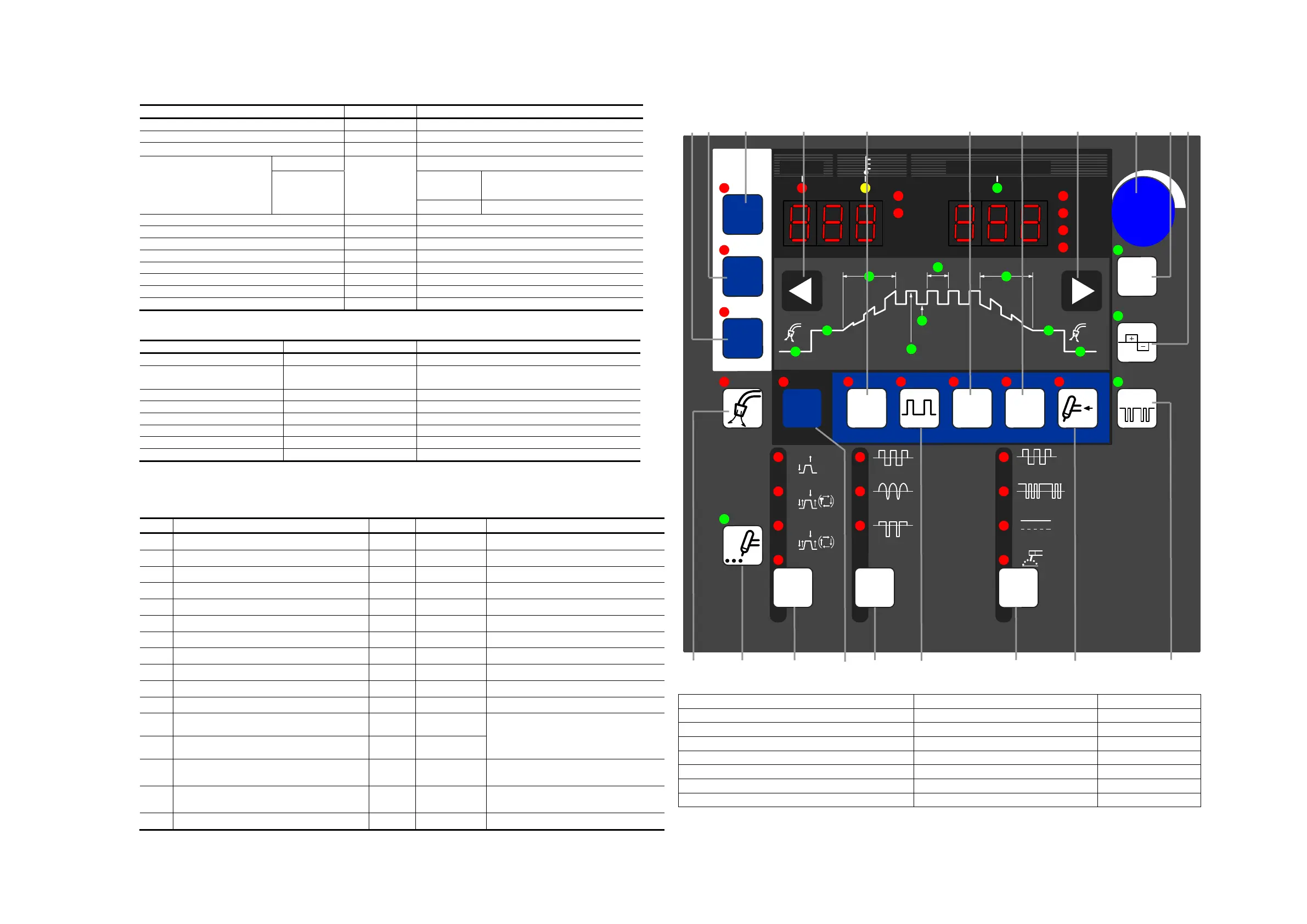
٨In reading the “Operation” paragraph described in “10.1 Basic Setup” and in the subsequent paragraphs,
consult this page to check the key location or the like.
[19][18] [17] [3] [11] [13]
[14]
[3] [4] [6] [7]
[16] [9] [5] [10] [2] [12] [1] [15] [8]
[1] WELDING METHOD change-over key [9] ARC SPOT TIME setting key [17] LOAD key
[2] AC WAVE change-over key [10] Function selection key [18] SAVE key
[3] Parameter selection key [11] INITIAL CURR. selection key [19] ENTER key
[4] Parameter adjusting knob [12] PULSE selection key
[5] CRATER FILL. key [13] LIFT START key
[6] AC FREQ. key [14] SLOPE selection key
[7] AC BALANCE key [15] TORCH change-over key
[8] AC-DC change-over frequency setup key [16] GAS CHECK key
* Further, F17 to F20 have the functions as well. For details, see 10.1.17 “Internal Functions”.
㧲
t
f
CRATER
FILL.
SPOT TIME
GAS
CHECK
OFF
ON
REPEAT
SPOT
WELDI NG
METHOD
ON ON ON ON WATER
TORCH
SLOPE
INIT IAL
CURR.
PULSE
LIFT
START
LOAD
SAVE
ENTER
ASec
Hz
%
JOB
MEMORY
JOB NO.
AC- TIG
DC- STI CK
AC- DC TI G
DC- TIG
PULSE CURR.
㧔
BASE CURR.
㧕
PULSE FREQ.
UP SLOPE
DOWN SLOPE
I NITI AL CURR. CRATER- FILL.
CURR.
WELDING CURR.
㧭㧯
WAVE
㧭㧯
FREQ.
AC- DC
FREQ.
STANDARD
SOFT
HARD
DC NO- LOAD VOLTAGEWARNI NG
T1 T2
AC BALANCE