3 | Specific installer safety instructions
Installer reference guide
18
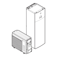
ERGA04~08E + EHVH04+08SU18+23E
Daikin Altherma 3 R F
4P629090-1C – 2022.08
WARNING
If the total refrigerant charge in the system is ≥1.84 kg (i.e. if the piping length is
≥27 m), you need to comply with the minimum floor area requirements for the
indoor unit. For more information, see "7.1.3 Installation site requirements of the
indoor unit"[464].
WARNING
▪ Only use R32 as refrigerant. Other substances may cause explosions and
accidents.
▪ R32 contains fluorinated greenhouse gases. Its global warming potential (GWP)
value is 675. Do NOT vent these gases into the atmosphere.
▪ When charging refrigerant, ALWAYS use protective gloves and safety glasses.
WARNING
The discharge pipes from the pressure relief valves MUST terminate in a safe and
visible position without forming any risk to persons in the vicinity.
WARNING
▪ Discharge piping, tundish, drain valves, etc. MUST be positioned away from any
electrical components.
▪ The discharge pipe away from the tundish MUST terminate in a safe, visible
position without forming any risk to persons in the vicinity.
WARNING
▪ Do NOT install any valves between the domestic hot water tank and relief valves/
expansion vessel.
▪ Do NOT install shut-off valves between the expansion relief valve and the
domestic hot water tank.
Electrical installation (see
"9Electrical installation"[
4
111]
)
DANGER: RISK OF ELECTROCUTION
WARNING
Electrical wiring connection method MUST be in accordance with the instructions
from:
▪ This manual. See "9Electrical installation"[4111].
▪ The wiring diagram of the outdoor unit, which is delivered with the unit, located
on the inside of the top plate. For a translation of its legend, see "16.3 Wiring
diagram: Outdoor unit"[4268].
▪ The wiring diagram of the indoor unit, which is delivered with the unit, located on
the inside of the indoor unit switch box cover. For a translation of its legend, see
"16.4Wiring diagram: Indoor unit"[4270].
WARNING
ALWAYS use multicore cable for power supply cables.
 Loading...