IOM 1242-2 • PATHFINDER
®
MODEL AWV CHILLERS 10 www.DaikinApplied.com
InsTallaTIon and applICaTIon ConsIderaTIons
Figure 8: Case 1 for AWV020-024
Figure 9: Case 1 for AWV026-030
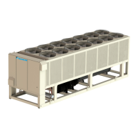
Case 2: Two Units Side-by-Side
For all models, there must be a minimum of 6 feet between
two units placed side-by-side; however, performance may
be affected at this distance due to air recirculation and
elevated condenser pressure. Assuming all service clearance
requirements are met, Figure 11 and Figure 12 depict Case 2
performance adjustments as the distance between two units
increases.
Figure 10: Two Units, Side-by-Side
Figure 11: Case 2 - Full Load Capacity Reduction
4 Feet
5 Feet
6 Feet
0.0%
0.2%
0.4%
0.6%
0.8%
1.0%
1.2%
1.4%
8 12 16 20 24
Height of Wall - Feet
% Full Load Capacity Reduction (AWV020-024)
4 Feet
5 Feet
6 Feet
0.0%
0.5%
1.0%
1.5%
2.0%
2.5%
3.0%
8 12 16 20 24
% Power Increase
Height of Wall - Feet
% Full Load Power Increase (AWV020-024)
4 Feet
5 Feet
6 Feet
0.0%
0.2%
0.4%
0.6%
0.8%
1.0%
1.2%
1.4%
1.6%
8 12 16 20 24
Height of Wall - Feet
% Full Load Capacity Reduction (AWV026-030)
4 Feet
5 Feet
6 Feet
0.0%
0.5%
1.0%
1.5%
2.0%
2.5%
3.0%
3.5%
8 12 16 20 24
% Power Increase
Height of Wall - Feet
% Full Load Power Increase (026-030)
D
0.0
1.0
2.0
3.0
4.0
5.0
6.0
6 8 10 12
Distance Between Units (ft)
Full Load Capacity Reduction
AWV008 AWV010 AWV012 AWV014
AWV016 AWV018 AWV020 AWV022
AWV024 AWV026 AWV028 AWV030