IOM 1242-2 • PATHFINDER
®
MODEL AWV CHILLERS 38 www.DaikinApplied.com
IsolaTor InformaTIon
IsolaTor InformaTIon
Isolator Installation
Transfer and place the unit as indicated in the Installation
section beginning on page 7. In all cases, set the unit in
place and level. If antiskid pads are used, do not use hold
down bolts. If hold down bolts are used, do not use antiskid
pads.
Mounting locations for each model conguration can be
found in the Dimensional Drawings section beginning on
page 35 or in the Submittal As-Built Drawings, available
from a Daikin Applied sales representative. Submittal As-
Built Drawings also specify the correct isolator color for each
mounting location, if ordered.
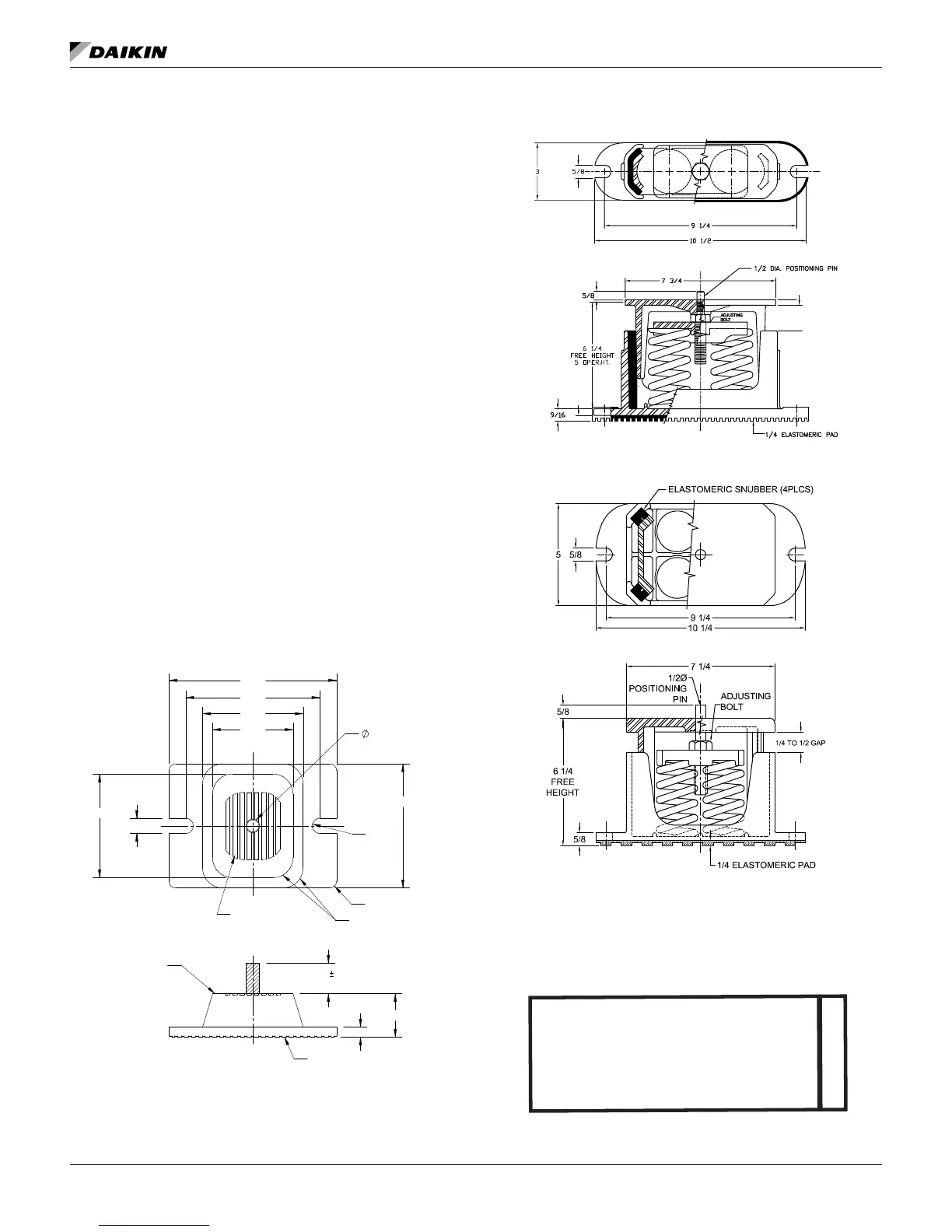
When spring isolators are required, install springs under the
main unit supports. Then unit should be set initially on shims or
blocks at the listed spring free height. Isolator springs should
not be loaded until all unit installation tasks are complete,
then the springs should be adjusted to the vendor listed
compression for the load point. When securing the isolator, do
not overtighten the mounting bolts. Overtightening may result
in cracking of the cast isolator housing and will have a negative
impact on the isolation effect.
Installation of spring isolators requires exible piping
connections and at least three feet of exible electrical conduit
to avoid straining the piping and transmitting vibration and
noise.
Neoprene wafe pads, supplied by customers, should be
mounted at the dened mounting point locations along the full
rail width.
Figure 42: Rubber-in-Shear Isolator Schematic
Figure 43: Spring Isolator - 2 Spring Schematic
Figure 44: Spring Isolator - 4 Spring Schematic
Figure 45: Mounting Location Reference Drawing
1.13
.25
APPROX.
MATERIAL
DURULENE
RAISED GRIP RIBS
1.63
.38
R4
R4
VM&C
RECESSED
GRIP RIBS
R.750 TYP.
.500-13NC-2B
VM&C
4.63
TYP.
.28R
3.00
3.75
5.00
6.25
3.87
TYP..56
R.250 TYP.
M1
M2
M3
M4
AWV - Approximate Mounting Locations
See Dimensional Drawing for exact location
M6
M5M9
M10 M8
M7