CIrCuIT funCTIons
www.DaikinApplied.com 61 IOM 1242-2 • PATHFINDER
®
MODEL AWV CHILLERS
When a capacity increase occurs, a time delay starts; and
when a capacity decrease occurs, a separate time delay starts.
While either of these delays is active, no normal capacity
changes will occur. The load and unload delay times are
calculated values.
Circuit State = Pumpdown - Speed command will drop 2 Hz
every second until reaching the minimum for the conguration.
Manual Speed Control
The speed of the compressor may be controlled manually.
Manual speed control is enabled via a set point with choices
of Auto or Manual. Another set point allows setting the
compressor speed. However, the resulting compressor speed
is still limited to the range from the minimum speed based on
conguration up to the Compressor Maximum Speed set point.
The compressor speed will be stepped up or down until it is
equal to the speed that corresponds to the manual speed set
point. Changes to the speed will be made as fast as allowed by
the calculated load and unload delays. Speed control may be
set to Manual only when circuit state is Start or Run.
Capacity control shall revert back to automatic control if either:
• the circuit state changes from Start or Run to another
state
• capacity control has been set to Manual for four hours
Load and Unload Delay
LWT Error determines the delays for load and unload
commands.
Table 48: Load and Unload Delay Conditions
LWT Error Delay
LWT Error > Startup Delta
T set point
Load command delay is 5
seconds
0.1°C ≤ LWT Error ≤
Startup Delta T set point
Load command delay will vary
from 5 seconds to 10 seconds
– (Stage Down Delta T
set point) ≤ LWT Error ≤
-0.1°C
Unload command delay will
vary from 3 seconds to 6
seconds
LWT Error < -(Stage Down
Delta T set point)
Unload command delay is 3
seconds
VR Solenoid Valve Control
There are three solenoid valves for changing volume ratio of
the compressor:
• 50 VR solenoid valve
• 75 VR solenoid valve
• 100 VR solenoid valve
The compressor should start with all three solenoid valves off.
After compressor has been running for at least 20 seconds, the
control logic will “stage” the solenoid valves. Table 49 shows
which VR solenoid valves are on at each stage as well as
stage up and stage down conditions. These staging conditions
must be active for 30 seconds to trigger each stage up or
down.
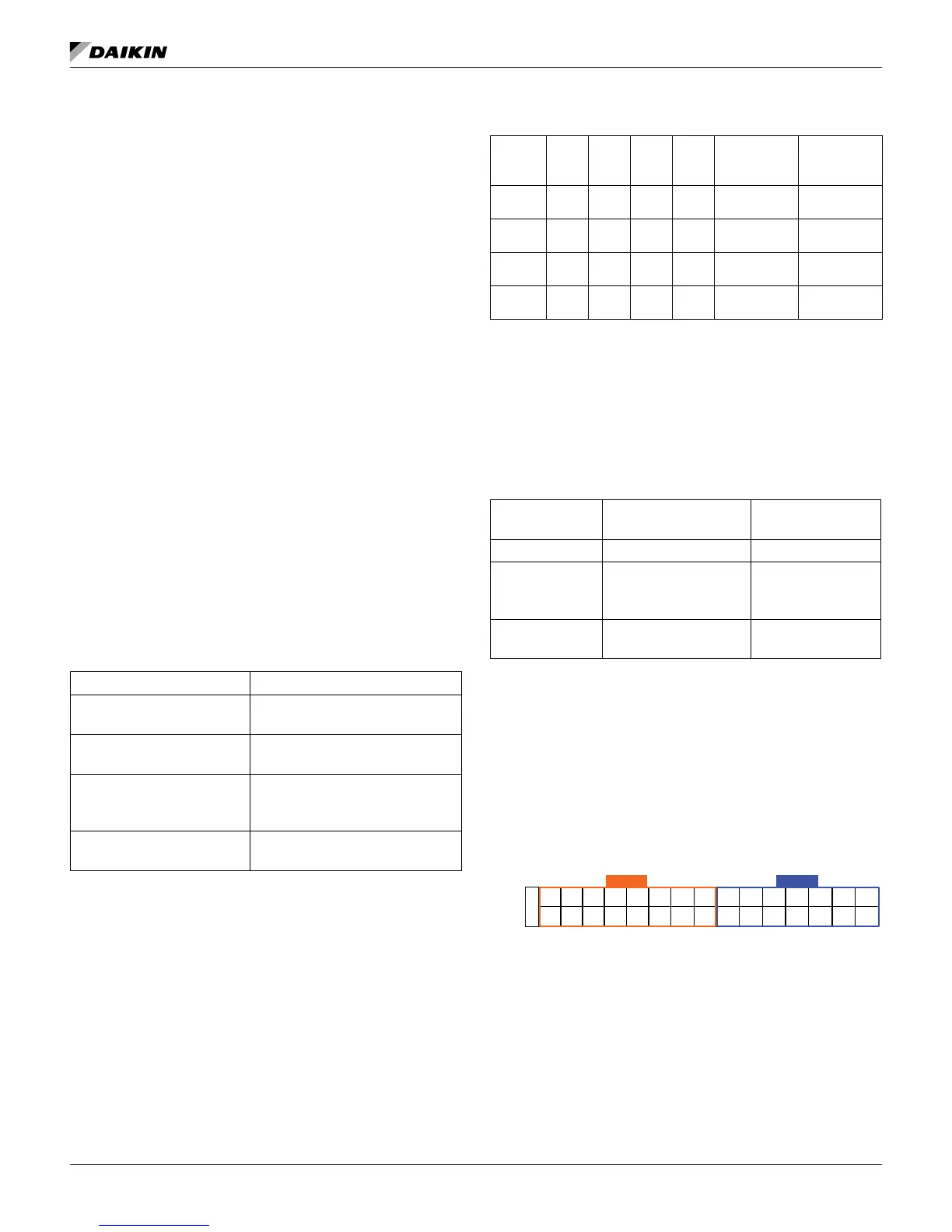
Table 49: VR Solenoid Valve Control Stages
Stage VR
50
VR
SV
75
VR
SV
100
VR
SV
Stage Up
Condition
Stage Down
Condition
0 1.6 Off Off Off
Pressure
Ratio > 2.10
n/a
1 1.8 On Off Off
Pressure
Ratio > 2.85
Pressure
Ratio < 1.90
2 2.4 Off On Off
Pressure
Ratio > 3.85
Pressure
Ratio < 2.65
3 3.1 On On On n/a
Pressure
Ratio < 3.65
When the circuit state becomes Pumpdown or Off, all VR
solenoids should be turned off.
Condenser Fan Control
Condenser fan control will vary in operation based on the Fan
VFD Conguration set point.
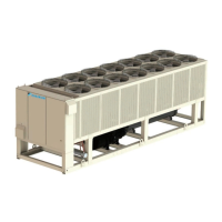
Table 50: Condenser Fan Control Congurations
Fan VFD
Conguration
Control Type Control
Mechanism
None Staging only Contactors
1st Fan VFD Staging and speed
control of 1st fan on
the circuit
Contactors and
VFD
All Fan VFD Staging and speed
control of all fans
Integrated VFD on
each motor
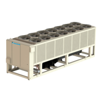
Physical Fan Layout
Fans are numbered as shown below (top view of chiller). Fan
numbers start on the left side of the circuit, closest to the
control box when facing the control box.
Circuit #1 fans start at 101 and can run through 116 depending
on the number of fans on the circuit. Circuit #2 fans start at 201
and can run through 214 depending on the number of fans on
the circuit.
Figure 63: Fan Numbering Diagram - Representative
NOTE: Number of fans vary by unit conguration
101
102
103
204
205
206
203
104
105
202
201
106
107
108
207
208
109
110
209
210
111
112
211
212
113
114
213
214
115
116
Control
Box
End
Circuit 1
Circuit 2