IOM 1242-2 • PATHFINDER
®
MODEL AWV CHILLERS 12 www.DaikinApplied.com
InsTallaTIon and applICaTIon ConsIderaTIons
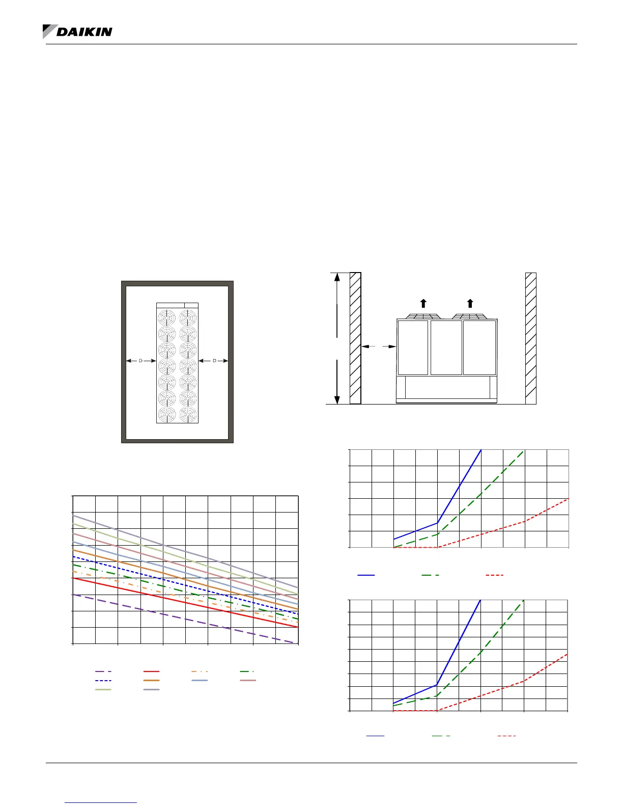
Case 4: Open Screening Walls
Decorative screening walls are often used to help conceal a
unit either on grade or on a rooftop. When possible, design
these walls such that the combination of their open area
and distance from the unit (see Figure 16) do not require
performance adjustment. If the wall opening percentage is less
than recommended for the distance to the unit, it should be
considered as a solid wall. It is assumed that the wall height is
equal to or less than the unit height when mounted on its base
support. If the wall height is greater than the unit height, see
Case 5: Pit/Solid Wall Installation. The distance from the sides
of the unit to the side walls must be sufcient for service, such
as opening control panel doors. For uneven wall spacing, the
distance from the unit to each wall can be averaged providing
no distance is less than 4 feet. Values are based on walls on all
four sides.
Figure 16: Allowable Wall Open Area
Figure 17: Case 4 - Adjustment Factor
Case 5: Pit/Solid Wall Installation
Pit installations can cause operating problems resulting from
air recirculation and restriction and require care that sufcient
air clearance is provided, safety requirements are met and
service access is provided. A solid wall surrounding a unit is
substantially a pit and this data should be used. Derates are
based on single chiller installation only.
Steel grating is sometimes used to cover a pit to prevent
accidental falls or trips into the pit. The grating material
and installation design must be strong enough to prevent
such accidents, yet provide abundant open area to avoid
recirculation problems. Have any pit installation reviewed by
the Daikin Applied sales representative prior to installation to
ensure it has sufcient air-ow characteristics and approved by
the installation design engineer to avoid risk of accident.
Figure 18: Pit Installation
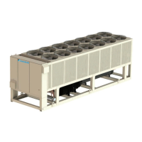
Figure 19: Case 5 for AWV008-010
4.0
5.0
6.0
7.0
8.0
9.0
10.0
11.0
12.0
13.0
0 10 20 30 40 50
Distance from Wall to Unit (ft)
% Open Wall Area
Wall Free Area vs. Distance
AWV008-010 AWV012-014 AWV016 AWV018
AWV020 AWV022 AWV024 AWV026
AWV028 AWV030
H
Control
Panel
D
0.0
1.0
2.0
3.0
4.0
5.0
6.0
0 8 10 12 13 14
% Capacity Reduction
Depth of Pit / Wall Height (ft)
Full Load Capacity Reduction (AWV008-010)
Distance = 6 ft Distance = 8 ft Distance = 10 ft
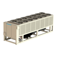
0.0
1.0
2.0
3.0
4.0
5.0
6.0
7.0
8.0
9.0
0 8 10 12 13 14
% Power Increase
Depth of Pit / Wall Height (ft)
Power Increase (AWV008-010)
Distance = 6 ft Distance = 8 ft Distance = 10 ft