IOM 1242-2 • PATHFINDER
®
MODEL AWV CHILLERS 14 www.DaikinApplied.com
InsTallaTIon and applICaTIon ConsIderaTIons
Chilled Water Piping
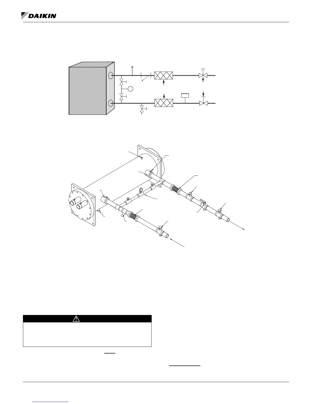
Figure 24: Typical Chilled Water Piping, Braze Plate
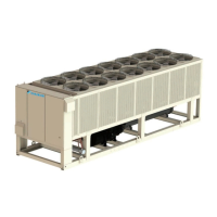
Figure 25: Typical Chilled Water Piping, Shell and Tube Evaporator
Startup procedures should conrm that the chilled water piping
system had been properly ushed out before being connected
to the chiller vessel.
All evaporators have OGS-type grooved water connections
(adhering to Standard AWWA C606) or optional ange
connections. The installing contractor must provide matching
mechanical connections. PVC and CPVC piping should not
be used. Be sure water inlet and outlet connections match
certied drawings and nozzle markings.
CAUTION
To prevent damage to the evaporator and potential chiller
failure, a supply strainer is required in the inlet water piping
which connects to the evaporator. This strainer must be
installed prior to operation of the chilled liquid pumps.
Field installed water piping to the chiller must include:
• A cleanable strainer installed at the water inlet to the
evaporator to remove debris and impurities before they
reach the evaporator. Install cleanable strainer within
5 feet (1500 mm) of pipe length from the evaporator
inlet connection and downstream of any welded
connections (no welded connections between strainer
and evaporator).
• AWV models require a strainer as specied in Inlet
Strainer Guidelines on page 15.
• A water ow switch must be installed in the horizontal
piping of the supply (evaporator outlet) water line to avoid
evaporator freeze-up under low or no ow conditions. The
ow switch may be ordered as a factory-installed option,
a eld-installed kit, or may be supplied and installed in the
eld. See page 16 for more information.
• Purge air from the water system before unit startup to
provide adequate ow through the evaporator.
• Adequate piping support, independent from the unit,
to eliminate weight and strain on the ttings and
connections.
It is recommended that the eld installed water piping to the
chiller include:
Air
Vent
Flow
Switch
Vibration
Eliminators
Drain
Outlet
Inlet
P
Isolation
Valves
Strainer
WELDED PIPE CONNECTIONS ARE NOT ALLOWED
BETWEEN THE STRAINER AND EVAPORATOR DUE
TO THE CHANCE OF SLAG ENTERING THE EVAPORATOR
LEAVING FLUID
TEMP. SENSOR
VENT
3/8” PIPE PLUG
VIBRATION
ELIMINATOR
FLOW
SWITCH
GATE
VALVE
FLOW
FLOW
GATE
VALVE
OUTLET
DRAIN
BALANCING
VALVE
VIBRATION
ELIMINATOR
WATER
STRAINER
VALVED
PRESSURE
GAUGE
PROTECT ALL FIELD PIPING
AGAINST FREEZING
INLET
WELDED PIPE CONNECTIONS ARE NOT ALLOWED
BETWEEN THE STRAINER AND EVAPORATOR DUE TO THE
CHANCE OF SLAG ENTERING THE EVAPORATOR