8 Installation Manual 3P581074-2D
DGE601A52
English
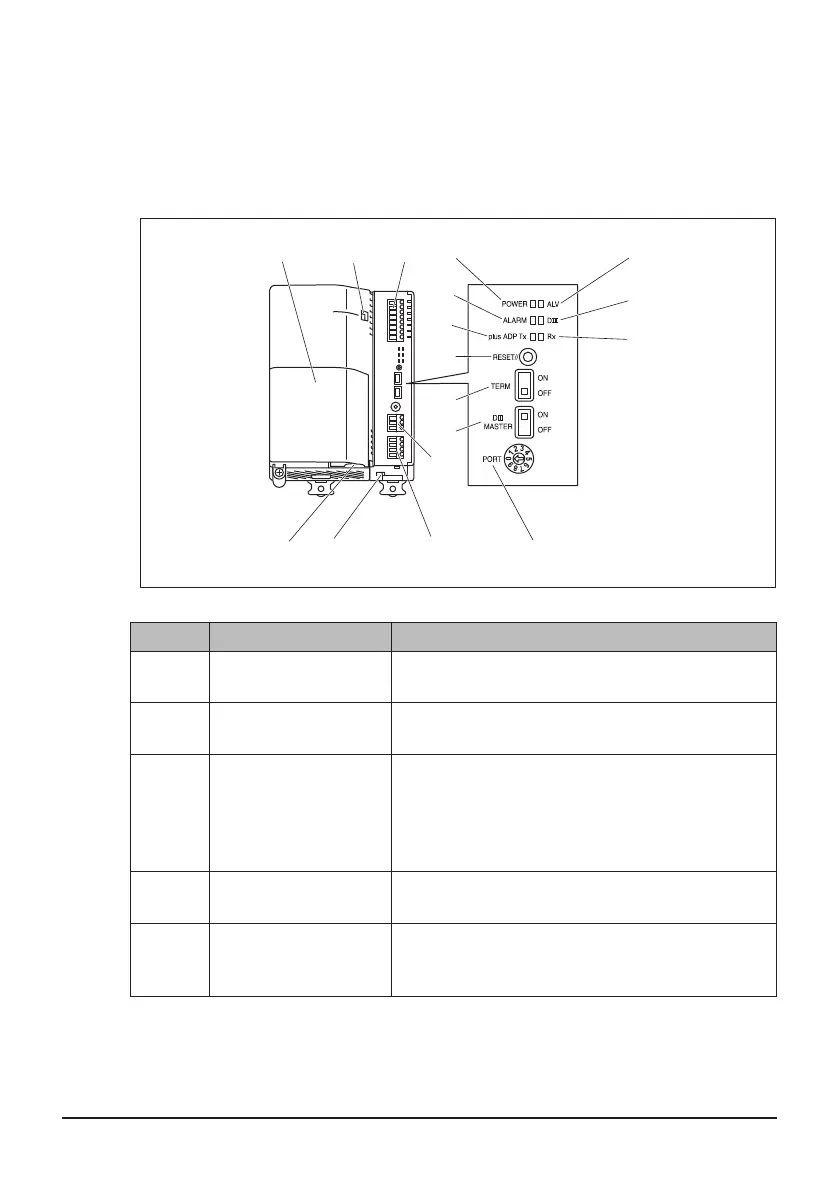
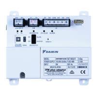
1.3.2 Front face
All the terminals used during installation are located on the front face of the DGE601A52.
The power supply terminals are covered with a terminal cover for safety.
In addition to these terminals, several switches and LEDs are also located on the front
face of the DGE601A52.
<Front face of DGE601A52>
A B G
F
Q
E H I
K
M
J
L
N
DC
O
P
Symbol Name Explanation
A
[Intake for power
supply cable]
Intake for power supply cable.
B [Inter-unit lock]
Knob for locking the power supply unit and
DGE601A53.
C [Power supply unit]
Terminals for the connection of the power supply.
These terminals are covered with a protective
cover.
A singe phase 100 to 240 V AC (at 50/60 Hz)
power supply voltage is required.
D [DC OUT] LED
LED (Green) When DC output is normal, this LED
is lit.
E [Di]
Terminals for stopping air conditioner operation
by an external signal in case of an emergency, or
for connecting electric energy meters.
01_EN_3P581074-2D.indd 8 2021/06/25 14:12:09



 To Next Page