Installation Manual 3P581074-2D
DGE601A52
33English
3.3 Connecting an emergency stop input device or electric
energy meters
The DGE601A52 can perform operations such as an emergency stop of the air condi-
tioners according to an external signal input device, and an electricity usage calculation
for each air conditioner according to the pulse inputs from a power meter.
WARNING
• Be sure to perform the operation during power-off conditions. Not doing so
may cause an electric shock.
• Do not clamp high-current cables together with low-current cables.
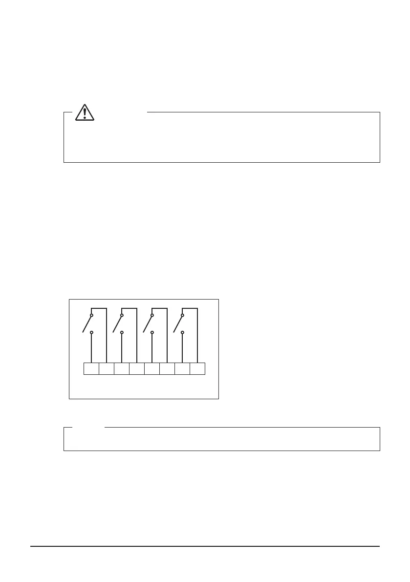
3.3.1 Terminals location and schematic connection diagram
Connect the contact input lines or pulse signal lines to the [i1] [i2] [i3] [i4] [CM] termi-
nals of Di located on the upper part of the front face.
Each terminal has a different function.
[i1] [i2] [i3] [i4] Pulse input, contact signal input
[CM] Common
However, the function settings for terminals ([i1] to [i4]) can be changed later. For how
to change the function settings, refer to the “Commissioning Manual”.
<Schematic drawing of Di connection>
CM
i1
CM
i2
CM
i3
CM
i4
Di
NOTE
When using open-collector type outputs, connect [CM] to the negative side.
01_EN_3P581074-2D.indd 33 2021/06/25 14:12:11