Installation Manual 3P581074-2D
DGE601A52
7English
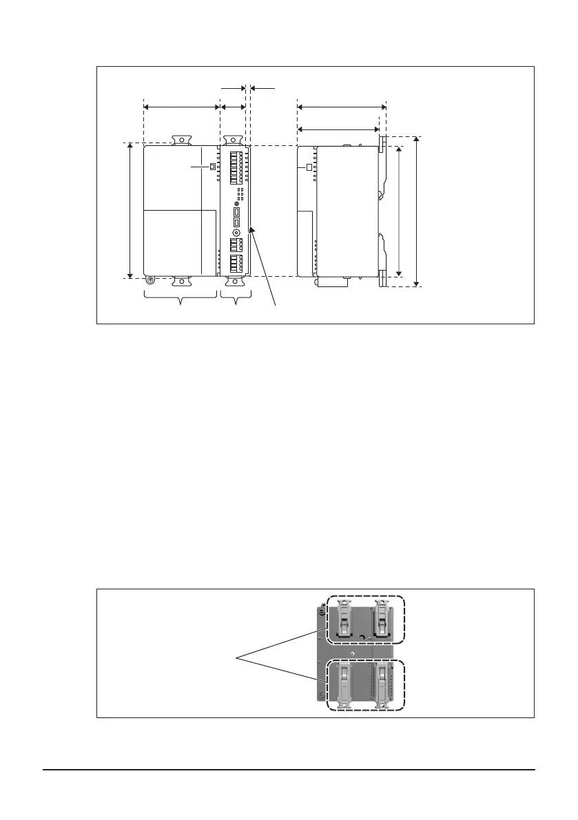
1.2 Understanding external dimensions
81.2 mm70 mm
25.2 mm
2 mm
120 mm
124 mm
74 mm
A B C
138mm
(When DIN rail lock is
“closed”)
146mm
(When DIN rail lock is
“open”)
A Power supply unit
B DGE601A53
C End cover
1.3 Understanding terminals and switches
Understand the arrangement of terminals and switches on the unit to facilitate the
installation procedure.
For details including the cable type, terminal size, and precautions, refer to “3. Electrical
Wiring”.
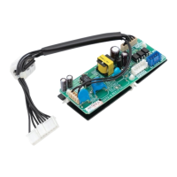
1.3.1 Rear face
On the rear face of the DGE601A52 there is a DIN rail lock for use when installing on a
DIN rail.
<Rear face>
A
A DIN rail lock
01_EN_3P581074-2D.indd 7 2021/06/25 14:12:09