Installation Manual 3P581074-2D
DGE601A52
23English
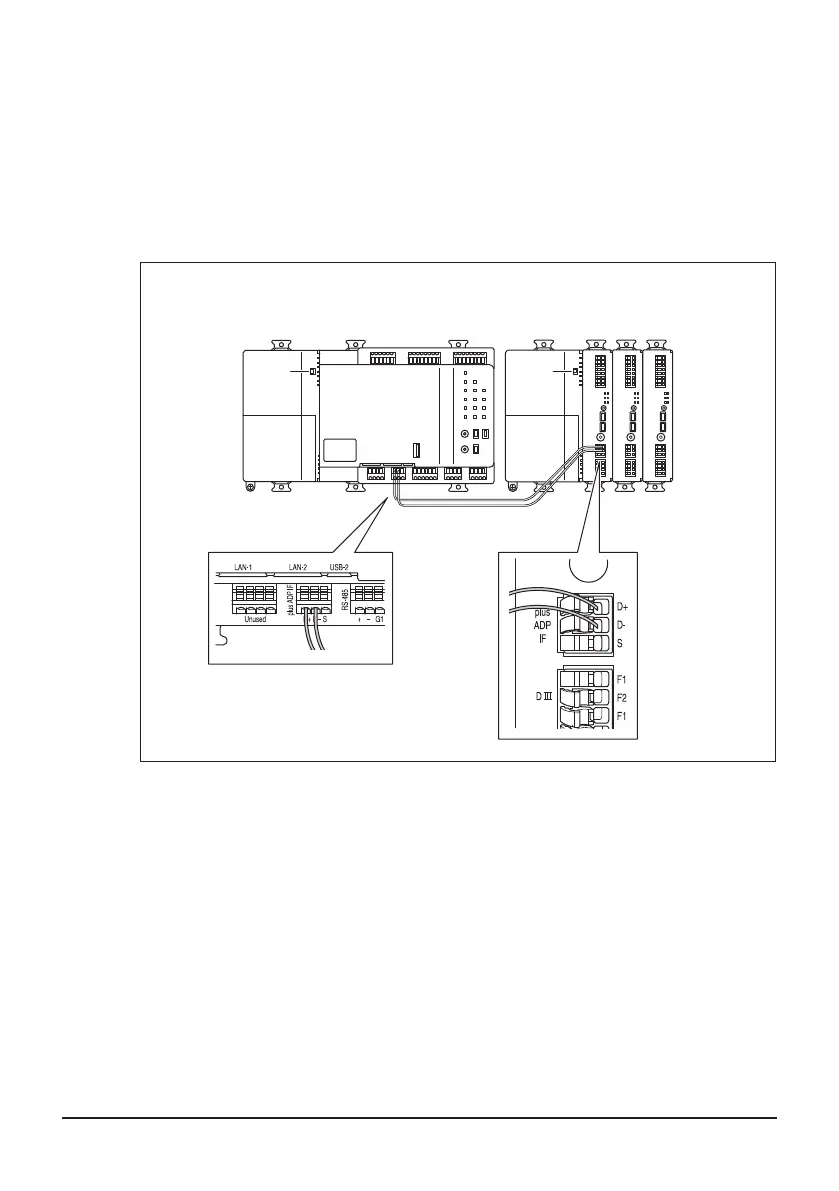
3.1.1 Terminals location and schematic connection diagram
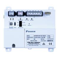
Connect the terminals located in the [plus ADP IF] section of the DGE601A52 to the
corresponding terminals located in the [plus ADP IF] section of your DGE601A51.
Note that these terminals have polarity.
Be sure to connect the positive wire to the “D+” terminal and the negative wire to the
“D–” terminal, respectively.
In addition, the DGE601A51 must be connected as a terminal to the wiring.
<Terminals location and schematic connection diagram>
A B E
DC
In case of connecting to the DGE601A51
A
DGE601A51 (For details, refer to “DGE601A51 Installation Manual (3P581074-1)”)
B DGE601A52
C plus ADP IF (DGE601A51)
D plus ADP IF (DGE601A52)
E DGE601A52/DGE601A53 on which termination resistor must be enabled
(For details on DGE601A53, refer to “DGE601A53 Installation Manual (3P583694-4)”.)
01_EN_3P581074-2D.indd 23 2021/06/25 14:12:10



 To Next Page