Do you have a question about the Daikin DGE601A52 and is the answer not in the manual?
Verify all DGE601A52 accessories are included as per the list provided.
Details the physical measurements and dimensions of the DGE601A52 unit for installation planning.
Describes the DIN rail lock mechanism located on the rear face of the DGE601A52.
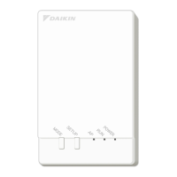
Details the various terminals, switches, and LEDs located on the front face of the DGE601A52.
Specifies requirements for the installation location and the correct mounting orientation of the unit.
Outlines the acceptable ambient temperature and humidity ranges for the DGE601A52 installation environment.
Provides an example of how to wire cables to the DGE601A52 unit.
Details the minimum clearances and space required for the proper installation of the DGE601A52.
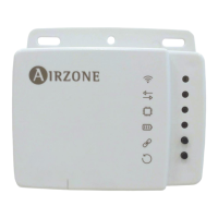
Lists other DAIKIN equipment that can be connected to the DGE601A52.
Step-by-step instructions for mounting the DGE601A52 onto a 35 mm DIN rail.
Procedures for safely detaching the DGE601A52 unit from a DIN rail.
Lists the specific accessory mounting parts required for securing the unit via screws.
Step-by-step instructions for securing the DGE601A52 unit into a control enclosure using screws.
Describes the process and steps involved in adding a DGE601A53 unit to the system.
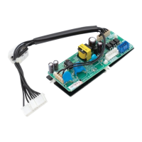
Shows terminal locations and wiring diagrams for connecting the DGE601A52 to a DGE601A51.
Specifies cable types, core thickness, and maximum length for DGE601A51 connections.
Procedures for setting unique addresses and configuring termination resistors for connected devices.
Identifies DIII-NET terminals and provides a schematic for connecting multiple air conditioners.
Details cable types, core thickness, and distance limits for DIII-NET communication.
Guidelines for setting master/slave roles and priority when using multiple centralised controllers.
Shows terminal locations and a schematic for connecting external emergency stop or energy meter devices.
Specifies cable types, core thickness, and length for digital input wiring.
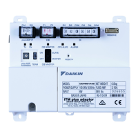
Identifies power supply terminals (L, N, Earth) and illustrates the connection schematic.
Details cable types, core thickness, voltage, power consumption, and breaker requirements for power connection.
Step-by-step guide to setting addresses using the BRC1H* wired remote controller.
Step-by-step guide to setting addresses using the BRC1E* navigation remote controller.
Instructions for setting the Airnet address of the outdoor unit directly via its controls.
How to set the demand address and enable demand control functionality on the outdoor unit.
Instructions on how to restart the DGE601A52 unit using the reset button.