72 Installation Manual 3P581074-2D
DGE601A52
English
5. Press the BS3 button 2 times to conrm the demand address setting.
Next, enable demand setting.
6. Press the BS2 button 12 times. (Select the setting item.)
7. Press the BS3 button.
You can now nd out the currently set value (enabled/disabled) by the LED (segment).
8. If it is disabled, press the BS2 button 1 time to enable it.
The LEDs and segments will be in the state shown below.
Setting items
LED (segment) display
Outdoor unit of the LED display
Outdoor unit of the
segment display
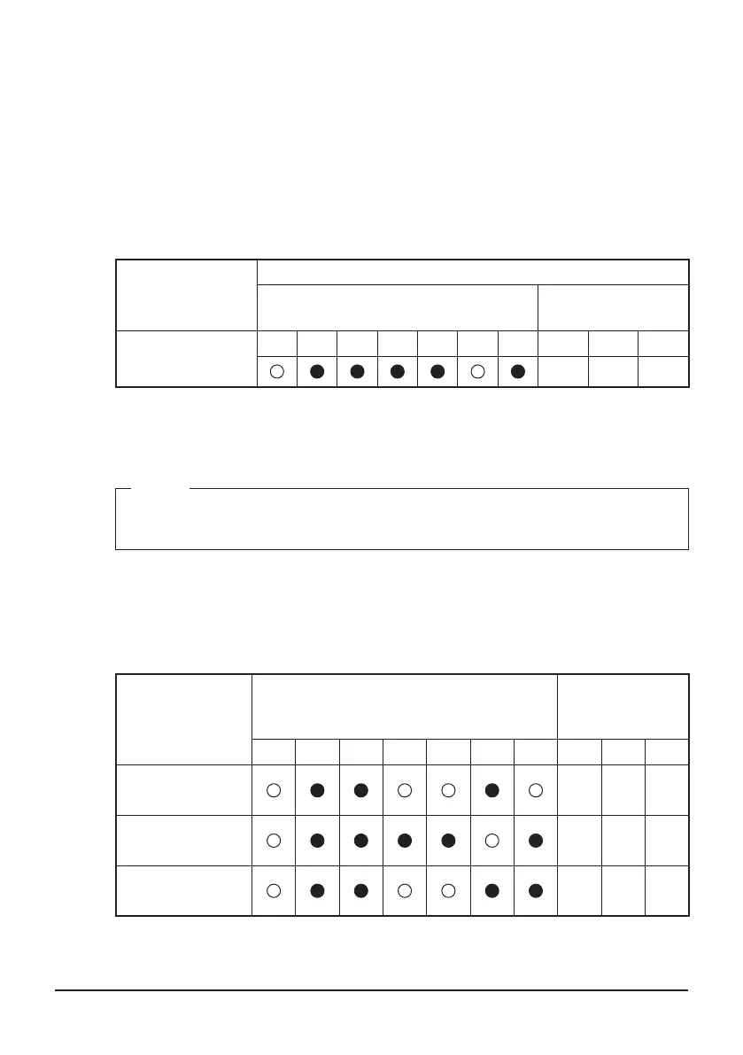
demand setting
(enabled)
H1P H2P H3P H4P H5P H6P H7P SEG1 SEG2 SEG3
0 0 1
9. Press the BS3 button 2 times to conrm the set value.
10. Press the BS1 button 1 time to return to the normal mode.
NOTE
If you want to use the demand control of the External Control Adapter for Outdoor
Unit, you do not need to perform this setting.
4.3.3 Setting items LED (segment) display
When you press the BS2 button and select setting items, the LED (segment) display
will be in the state shown below.
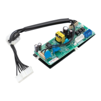
Setting items
Outdoor unit of the LED display
Outdoor unit of
the segment
display
H1P H2P H3P H4P H5P H6P H7P SEG1 SEG2 SEG3
Outdoor unit AIRNET
address setting
2 1 3
demand address
setting
2 0 2
demand setting
Enabled/Disabled
2 1 2
The address setting of the outdoor unit is complete.
The installation work of DGE601A52 is complete.
01_EN_3P581074-2D.indd 72 2021/06/25 14:12:21