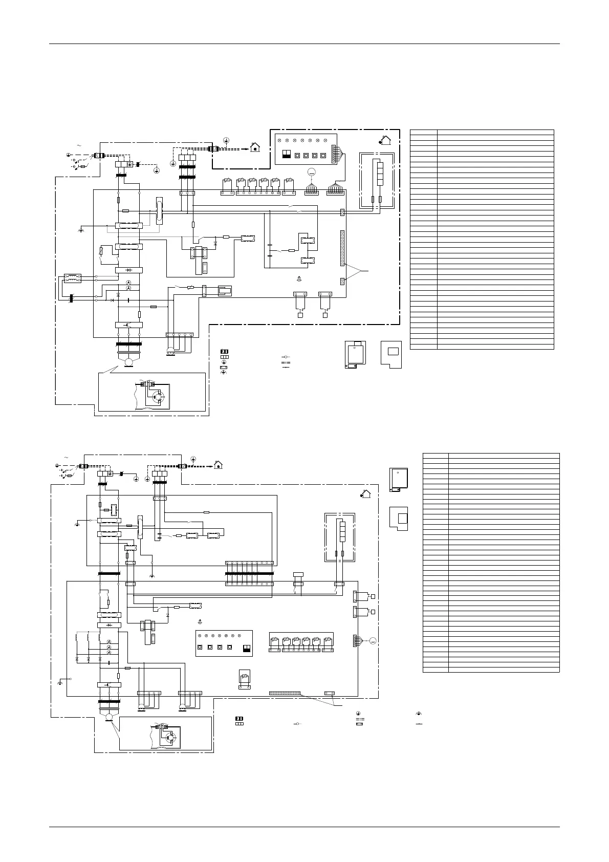
ESIE15-13B Wiring Diagrams
Appendix 199
2. Wiring Diagrams
2.1 Outdoor Unit
2.1.1 RZQG71L
2.1.2 RZQG100-140L
R6
K15R
TC
RC
K10R
K11M
+
C1
V3D
V1T
X25A
PS
K13R
X804A
X806A
X805A
X106A
M1F
MS
HAP
H1PH3PH5PH7P
H2P H4P H6P
BS1
BS2 BS3 BS4
ON
DS1
2
1
OFF
X11A
X12A
R3T
t°
R1T
t°
X13A
R6T
t°
R2T
t°
R4T
t°
R5T
t°
M
S1PH
P>
S1PL
P<
K1R
Y1S
A2P
A1P
W
V
U
X31A
X32A
X21A
Y1E
C2
C3
A1P
L1R
X1M
HAP
F8U
F7U
E1H
X6A
6
V2R
N
220-240V
1N 50Hz
L
NA
L
N
LA
RED BLU
X803A
231
Z3
C
N=
1
X1M
X1M
Q1DI
F2U
F1U
Z1F
Z3F
E1
Z2F
V2T
V2D
+
-
HR1
HR3
L1R
HR4
HR2
Z5
C
N=
6
V1R
WV
RED
~
Z4
C
N=
4
U
WHT
V
W
U
3
MS
BLU
M1C
F6U
R2
R4
+-
V1D
R5
+t°
R8T
X6A
X77A
X28A
X5A
8
X205A
A2P
R7T
+t°
WHT
BRN
PPL
RED
Z2
C
N=
3
Z6
C
N=
1
Z1
C
N=
5
BLK
WHT
RED
K14R
K2R
GRN/YLW
GRN
X502A
A1P
A2P
BS1 ~ BS4
C1 ~ C3
DS1
E1H
F1U ~ F2U
F6U
F7U ~ F8U
H1P ~ H7P
HAP
K1R
K2R, K10R
K11M
K13R ~ K15R
L1R
M1C
M1F
Q1DI
R2, R5, R6
R1T
R2T
R3T
R4T
R5T
RC
S1PH
S1PL
TC
V1D ~ V3D
V1R
V2R
V1T ~ V2T
X1M
Y1E
Y1S
Z1C ~ Z6C
Z1F ~ Z3F
Printed circuit board (main)
Printed circuit board
Capacitor
DIP switch
Fuse (T 3.15A / 250V)
Fuse (F 1.0A / 250V)
Light-emitting diode (service monitor is orange)
Light-emitting diode (service monitor is green)
Magnetic relay (Y1S)
Magnetic relay
Magnetic relay
Magnetic contactor
Reactor
Motor (compressor)
Switching power supply
Resistor
Thermistor (air)
Thermistor (discharge)
Thermistor (heat exchanger)
Thermistor (heat exchanger middle)
Thermistor (liquid)
Thermistor (suction)
Signal receiver circuit
High pressure switch
Low pressure switch
Signal transmission circuit
IGBT power module
Diode module
Terminal strip
Electronic expansion valve
Solenoid valve (4-way valve)
Noise filter (ferrite core)
Noise filter
Push-button switch
Diode
Insulated Gate Bipolar Transistor (IGBT)
R6T
PS
Earth leakage circuit breaker (30mA)
Bottom plate heater (option)
Notes
1.
2.
3.
4.
5.
6.
N: NeutralL: Live
Field wiring
Terminal
Colours: blk:black; red:red; blu:blue; wht:white; grn:green; ylw:yellow; brn:brown; org:orange; pnk:pink
This wiring diagram applies only to the outdoor unit.
Refer to the wiring diagram sticker (on the back of the front plate) for how to use the BS1 - BS4 and DS1 switches.
Protective earth
Option
Connector
Connection
When operating, do not short-circuit protection device(s) S1PH, S1PL.
Refer to the service manual for instructions on how to set the selector switches (DS1). The factory setting of all switches is OFF.
Terminal strip
2D089497B
7.
Refer to the combination table and the option manual for how to connect the wiring to __________ and __________.
Position of compressor terminal
Position of elements
Electronic component assembly
Front view Rear view
Indoor
Outdoor
Noiseless earth
R7T ~ R8T
Motor (fan)
Thermistor (Positive Temperature Coefficient)
8.
See note 8.
SEE
NOTE 7
Fuse
N
220-240V
1N 50Hz
L
NA
L
N
LA
F2U
F1U
Z1F
Z1
C
N=
2
Z6
C
N=
1
RED BLU
GRN/YLW
Z4F
F4U
Z3F
X803A
R3
K15R
TC RC
K14R
R4
Z2F
F3U
X98A
NCLC
E2
X802A
E3
X99A
RED BLU GRN
Z3
C
N=
2
NB
LB
X801A
Z5
C
N=
1
R1
Z6F
K10R
K11M
L3R
L2RL1R
+
C1
V3DV2DV1D
V2T
V1T
V3T
X25A X28A
R5
PS
K13R
V4D
X804A
X806A
X805A
F6U
R2
+-
V1R
WV
RED
~
Z4
C
N=
6
U
WHT
V
W
U
3
MS
BLU
M1C
E1
X107A
M2F
MS
X106A
M1F
MS
HAP
H1P H3P H5P H7P
H2P H4P H6P
BS1
BS2
BS3
BS4
ON
DS1
2
1
OFF
X111A
R7T
t°
X11A
X12A
R3T
t°
R1T
t°
X13A
R6T
t°
R2T
t°
R4T
t°
R5T
t°
M
S1PH
P>
S1PL
P<
GRN
K1R
K4R
Y1S
A2P
A1P
W
V
U
231
Z2
C
N=
2
X1MX1M
X31A
X32A
X21A
Y1E
C3
C2
A1P
A2P
X1M
HAP
F8UF7U
E1H
X77A
X6A
6
Q1DI
V2R
BLK
BLU
RED
Z5F
X502A
GRN
Notes
1.
2.
3.
4.
5.
6.
N: NeutralL: Live
Field wiring
Terminal
Colours: blk:black; red:red; blu:blue; wht:white; grn:green; ylw:yellow; brn:brown; org:orange; pnk:pink
This wiring diagram applies only to the outdoor unit.
Refer to the wiring diagram sticker (on the back of the front plate) for how to use the BS1 - BS4 and DS1 switches.
Protective earth
Noiseless earth
Option
Connector
Connection
When operating, do not short-circuit protection device(s) S1PH, S1PL.
Refer to the service manual for instructions on how to set the selector switches (DS1). The factory setting of all switches is OFF.
Terminal strip
A1P
A2P
BS1 ~ BS4
C1 ~ C3
DS1
E1H
F1U ~ F4U
F6U
F7U ~ F8U
H1P ~ H7P
HAP
K1R
K10R
K11M
K13R ~ K15R
K4R
L1R ~ L3R
M1C
M1F
M2F
Q1DI
R1 ~ R5
R1T
R2T
R3T
R4T
R5T
R7T
RC
S1PH
S1PL
TC
V1D ~ V4D
V1R
V2R
V1T ~ V3T
X1M
Y1E
Y1S
Z1C ~ Z6C
Z1F ~ Z6F
Printed circuit board (main)
Printed circuit board
Capacitor
DIP switch
Fuse (T 5.0A / 250V)
Fuse (F 1.0A / 250V)
Light-emitting diode (service monitor is orange)
Light-emitting diode (service monitor is green)
Magnetic relay (Y1S)
Magnetic relay
Magnetic relay
Magnetic contactor
Reactor
Motor (compressor)
Switching power supply
Resistor
Thermistor (air)
Thermistor (discharge)
Thermistor (heat exchanger)
Thermistor (heat exchanger middle)
Thermistor (liquid)
Thermistor (suction)
Signal receiver circuit
High pressure switch
Low pressure switch
Signal transmission circuit
IGBT power module
Diode module
Terminal strip
Electronic expansion valve
Solenoid valve (4-way valve)
Noise filter (ferrite core)
Noise filter
Push-button switch
Magnetic relay E1H (option)
Motor (fan)(upper)
Motor (fan)(lower)
Diode
Position of compressor terminal
Position of elements
Electronic component assembly
2D088865C
Insulated Gate Bipolar Transistor (IGBT)
Front view
Rear view
Indoor
Outdoor
7. Refer to the combination table and the option manual for how to connect the wiring to __________ and __________.
R6T
Thermistor (fin)
SEE NOTE 7
SEE NOTE 7
PS
Earth leakage circuit breaker (30mA)
Bottom plate heater (option)
Fuse

 Loading...