Function of Main Components and Thermistors ESIE15-13B
28 Function and Control
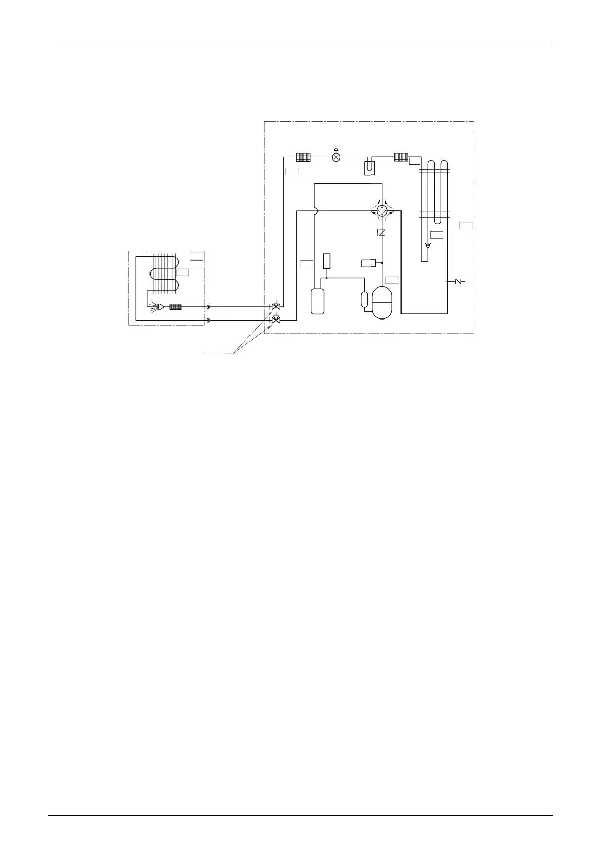
1. Function of Main Components and Thermistors
RZQG-L9V1
Pair application
Notes:
1. The pipes between the branch and the indoor units should have the same size as the indoor
connections.
2. The check valve is only present in following models: RZQG71L, RZQSG100L and
RZQSG125L.
* This thermistor is near the el. compo. box.
*
R4T
R3T
R6T
R2T
R1T
R5T
R2T
R3T
R1T
Filter
Filter
Filter
(C) Four way valve
Field piping ø9.5
C1220T-O
Field piping ø15.9
Accumulator
PCB Cooling
Distributor
(A) Compressor
C1220T-O
Indoor unit
Outdoor unit
Stop valve
(with service port 5/16" flare)
Outdoor
heat exchanger
Indoor
heat
exchanger
(B) Electronic
expansion valve
Compressor
Accumulator
Pressure
switch
(high)
Service
port
(5/16"
flare)
Check valve
Pressure
switch
(low)

 Loading...