Printed Circuit Board Connector Wiring Diagram SiBE01-503
10 Printed Circuit Board Connector Wiring Diagram
1. Printed Circuit Board Connector Wiring Diagram
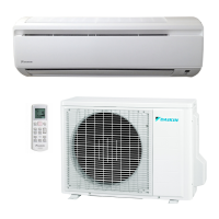
1.1 Indoor Unit
Connectors
Note: Other designations
1) S1 Connector for fan motor
2) S2, S4 Connector for transformer
3) S5 Connector for thermal fuse
4) S6 Connector for swing motor (horizontal blades)
5) S7 Connector for fan motor (Hall IC)
6) S26 Connector for control PCB
7) S27 Connector for signal receiver PCB
8) S32 Connector for indoor heat exchanger thermistor
9) S33 Connector for outdoor heat exchanger thermistor
10) H1 Connector for compressor (outdoor unit)
11) H2, H4 Connector for four way valve (outdoor unit)
12) H3 Connector for fan motor (outdoor unit)
13) H5 Connector for power supply (outdoor unit)
1) V1, V2 Varistor
2) JA Address setting jumper
JC Power failure recovery function (auto restart)
∗
Refer to page 107 for detail.
3) SW1 Forced operation ON/OFF switch
4) LED1 LED for operation (green)
5) LED2 LED for timer (yellow)
6) LED A LED for service monitor (green)
7) FU1 Fuse (3.15A)
8) RTH Room temperature thermistor
 Loading...