Installation and operation manual
9
FWEC2
Advanced electronic controller
FC66002764
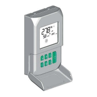
NON-SERIOUS ALARMS
■ Code A03 = water sensor error
■ Code A04 = remote humidity probe error (only if a remote
temperature probe is installed)
■ Code A05 = internal humidity probe error
N.B.: the alarm code is displayed only when the thermostat
is switched off
MODBUS
The protocol implemented in the controller is Modbus RTU
(9600, N, 8, 2) on RS485
FUNCTIONS IMPLEMENTED
■ 0x03 : Read Holding Registers
■ 0x04 : Read Input Registers
■ 0x10 : Write Multiple registers
EXCEPTIONS IMPLEMENTED
Exception Code 02: Invalidate data address
LIST OF SUPERVISION PARAMETERS
ADDRESS REGISTER TYPE U.M.
0
Status R -
1
Speeds R -
2
Air temperature R [°C/10]
3
Humidity R %
4
Water temperature R [°C/10]
5
P00: Confi guration R -
6
P05: Confi g. DIN R -
7
T. Active setpoint R [°C/10]
8
T. User setpoint R [°C/10]
9
LCD version R -
50
Digital 1 R/W -
51
- R/W -
52
Setpoint - Cooling R/W [°C/10]
53
Setpoint - Heating R/W [°C/10]
54
Minimum Setpoint – Cool. R/W [°C/10]
55
Maximum Setpoint – Cool. R/W [°C/10]
56
Minimum Setpoint – Heat. R/W [°C/10]
57
Maximum Setpoint – Heat. R/W [°C/10]
58
Speeds R/W -
59
Economy Correction R/W [°C/10]
DESCRIPTION OF READ-ONLY REGISTERS [R]
■ “Staus” “REGISTER”
H
Bit 15 Bit 14 Bit 13 Bit 12 Bit 11 Bit 10 Bit 9 Bit 8
- - P04 Deum P06 P07 DI2 DI1
L
Bit 7 Bit 6 Bit 5 Bit 4 Bit 3 Bit 2 Bit 1 Bit 0
Vh Vc
Alarm
MinT Eco P01 S/W On/Off
- On/Off: unit status (0: Off, 1=On)
- S/W: operation mode (0: S=cooling,1:W=heating)
- P01: “on unit/wall-mounted” parameter
- Eco: Economy logic active
- Min.T: Minimum Temperature logic selected
- Alarm: general alarm indication (activated when any of
the managed alarms is triggered)
- Vc: status of digital output Vc
- Vh: status of digital output Vh
- DI1: logical value of dig. input 1 (the physical status of the
input depends on the associated logic)
- DI2: logical value of dig. input 2 (the physical status of the
input depends on the associated logic)
- P07: “DIN 2 Logic” parameter
- P06: “DIN 1 Logic” parameter
- Dehum: dehumidifi cation ON (0:no, 1:yes)
- P04: “water probe present” parameter
■ “SPEED” REGISTER: current operating speed of the
indoor unit
- 0: fan OFF
- 1: extra-low speed
- 2: low speed
- 3: medium speed
- 4: high speed
■ “AIR TEMPERATURE” REGISTER: room temperature
read by the controller and shown on the display (N.B.:
this temperature corresponds to the reading of the remote
probe if the controller is located on the unit, or the read-
ing of the internal probe in the case of a wall-mounted
controller and remote probe disconnected)
■ “HUMIDITY” REGISTER: room humidity read by the
controller via the probe associated with the temperature
probe used
■ “WATER TEMPERATURE” REGISTER: value read by the
water probe (SW)
■ “P00” Register: “Controller confi guration” parameter
■ “T. ACTIVE SETPOINT” Register: setpoint used for tem-
perature control
■ “T. USER SETPOINT” Register: setpoint programmed by
the user (it may differ from the active setpoint due to cor-
rections based on economy logics,…or use of the setpoint
imposed by the supervision software)
■ “LCD VERSION” Register : defi nes the controller type and
software version installed (0xHHSS: HH: ASCII character,
SS:sw version)
Thermostat OFF Thermostat ON