Daikin IM 696-4 35
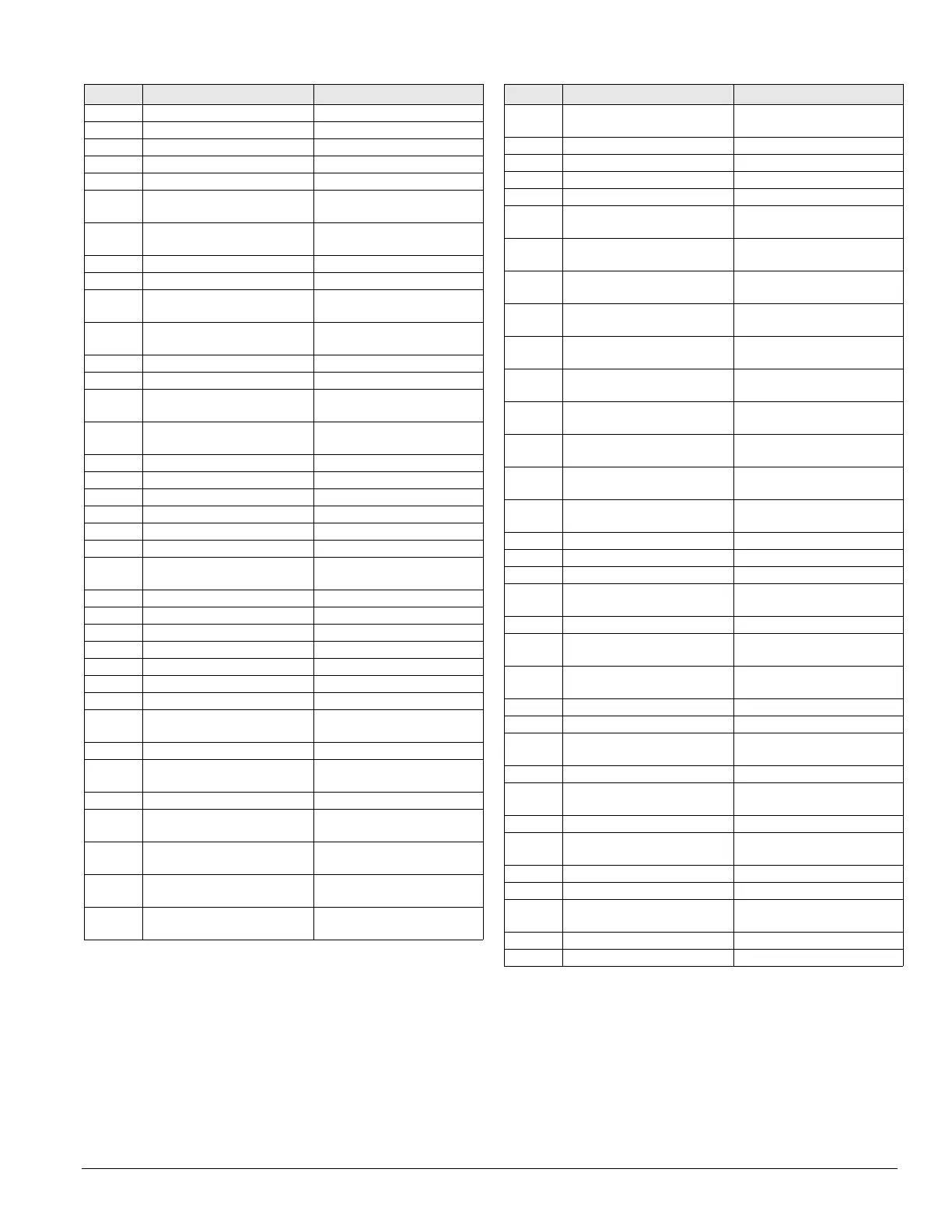
Typical Wiring Diagrams
GRD Ground All control boxes
GV1 Gas valve, pilot Heat section, gas
GV2 Gas valve, main/safety Heat section, gas
GV3 Gas valve, redundant/safety Heat section, gas
GV4–8 Gas valve, main, hi turn down Heat section, gas
HL1–10 Hi-limits, pwr, elec heaters (top
bank)
Heat section, electric
HL11–20 Hi-limits, pwr, elec heaters
(bot. bank)
Heat section, electric
HL22 Hi-limits, gas heat (pre-filters) Supply fan section
HL23 Hi-limits, gas heat (final filters) Final filter section
HL31–40 Hi-limits, ctl. elec heaters (top
bank)
Heat section, electric
HL41–50 Hi-limits, ctl. elec heaters (bot.
bank)
Heat section, electric
HP1–4 Hi-pressure controls, refrig On compressors
HP5 Hi-pressure controls, gas Heat section, gas
HS1 Heat switch, electric heat
shutdown
Main control box
HS3 Heat switch, electric heat
deadfront interlock
Electric heat box
HTR1–6 Crankcase heaters On compressors
HTR65 Heater, sump Evap. condenser section
HTR66 Heater, vestibule Evap. condenser vestibule
HUM1 Humidstat sensor Energy recovery section
IT Ignition transformer Gas heat box
LAT Leaving air temperature sensor Energy recovery section
LP1, 2 Low-pressure controls,
refrigeration
On compressors
LP5 Low-pressure control, gas Heat section, gas
LR10 Line Reactor, supply fan Inverter bypass box
LR20 Line reactor, return/exhaust fan Inv. bypass/main cont. box
LS1, 2 Limit switch, low fire, high fire Gas heat box
LT10–23 Light, cabinet sections Supply fan section
M1–8 Contactor, compressor Main/cond. control box
M10 Contactor, supply fan Main control box
M11–18 Contactor, condenser fans,
circuit #1
Main/cond. control box
M20 Contactor, return fan Main control box
M21–28 Contactor, Condenser fans,
circuit #2
Main/cond. control box
M29 Contactor, burner motor Gas heat box
M30 Contactor, reversing, invertor
bypass, supply fan
Inverter bypass box
M31–39 Contactor, electric heat (top
bank)
Electric heat box
M40 Contactor, reversing, Invertor
Bypass, Return Fan
Inverter bypass box
M41–50 Contactor, electric heat (bot.
bank)
Electric heat box
ID Description Standard location
M60 Contactor, energy recovery
wheel
Main control box
M64 Contactor, sump pump Main/cond. control box
M65 Contactor, sump heater Main/cond. control box
MCB Microprocessor circuit board Main control box
MJ Mechanical Jumper All control boxes
MMP1–8 Manual motor protector,
compressors
Main/cond. control box
MMP10 Manual motor protector, supply
fan
Main control box
MMP11–
18
Manual motor protector, cond.
fans, ckt#1
Main/cond. control box
MMP20 Manual motor protector, return
fan
Main control box
MMP21–
28
Manual motor protector, cond.
fans, ckt#2
Main/cond. control box
MMP30 Manual motor protector, invrtr.
bypass, sup. fan
Inverter bypass box
MMP40 Manual motor protector, invrtr.
bypass, ret. fan
Inverter bypass box
MMP51,
52, 53
Manual motor protector,
exhaust fan(s)
Prop exhaust box
MMP60 Manual motor protector,
energy recovery wheel
Main control box
MMP64 Manual motor protector, sump
pump
Main/RCE control box
MP1–6 Motor protector, compr.#1-6 On compressors
OAE Outside air enthalpy sensor Economizer section
OAT Outside air temperature sensor Economizer section
OP1–4 Oil pressure controls,
compr.#1-4
Condenser section
PB1, 2 Power block, power distribution Main control box
PB3 Power block, power
distribution, electric heat
Electric heat box
PB4 Power block, power
distribution, condenser
Condenser control box
PB9, 10 Power block, supply fan Junction box, split unit
PB11, 12 Power block, power distribution Main control box
PB19, 20 Power block, return/exhaust
fan
Junction box, split unit
PC5 Pressure control, clogged filter Pre filter section
PC6 Pressure control, clogged final
filter
Final filter section
PC7 Pressure control, proof airflow Supply fan section
PC8 Pressure control, minimum
airflow
Coil section, cool
PC12, 22 Pressure control, Fantrol Condenser section
PM1 Phone modem Main control box
PS1, 2 Pumpdown switches, refrig
circuits
Main/cond. control box
PS3 Pumpdown switch, RFS only Main control box
PVM1, 2 Phase voltage monitor Main control box
ID Description Standard location