36 Daikin IM 696-4
Typical Wiring Diagrams
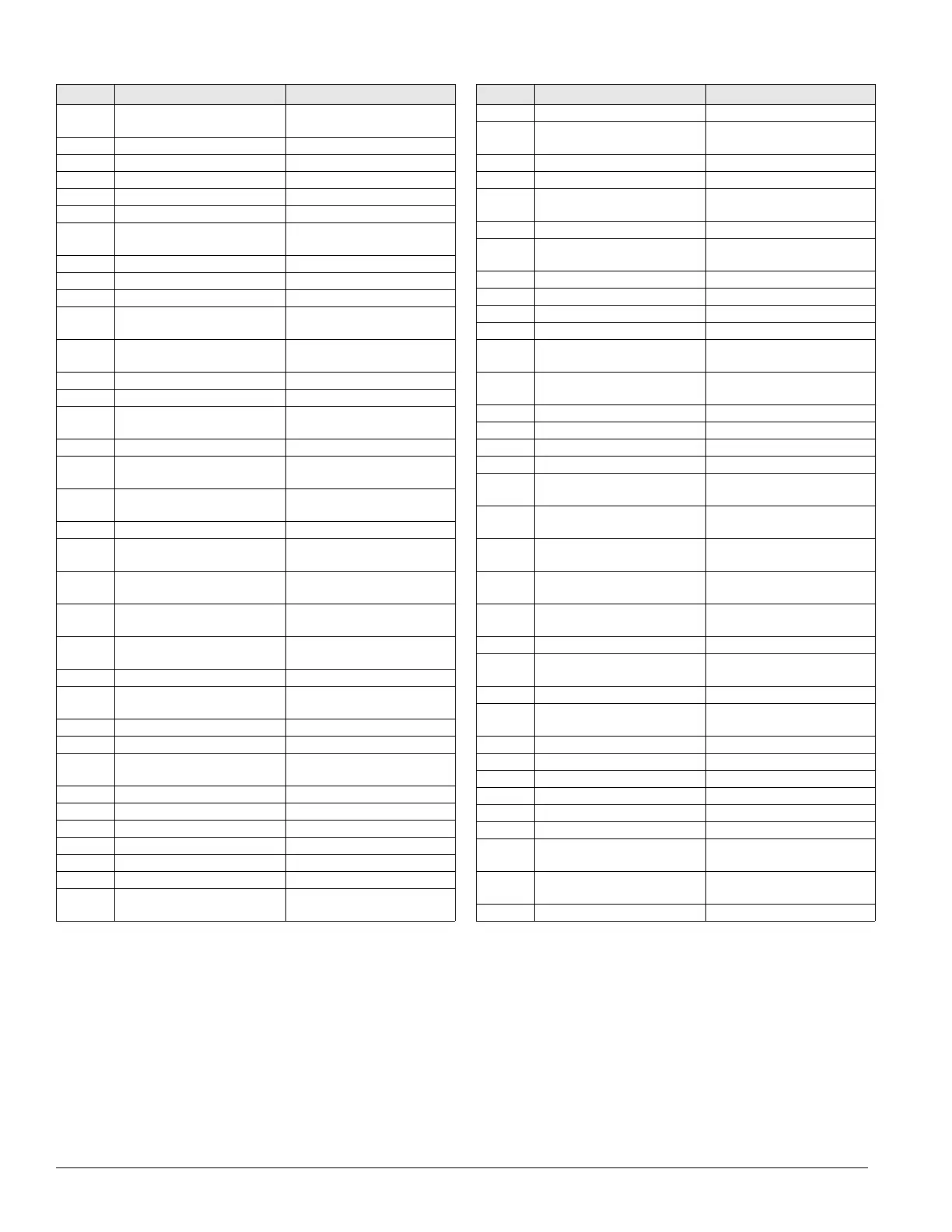
PVM4 Phase voltage monitor,
condenser
Condenser control box
R1, 2 Relay, hi pressure reset Main/cond. control box
R3, 4 Relay, hi pressure delay Main/cond. control box
R5–8 Relay, safety, cool fail Main/cond. control box
R9, 10 Relay, compressor lockout Main/cond. control box
R11, 12 Relay, Speedtrol fan cycling Main/cond. control box
R20 Relay, Heat, gas/ steam/ hot
water
Gas heat/main cont. box
R21, 22 Relay, heat, gas (hi-turn down) Gas heat box
R23 Relay, heat, gas & electric Gas/electric heat box
R24 Relay, heat alarm, gas Main control box
R25 Relay, heat, gas, start supply
fan inverter
Main control box
R26 Relay, isol/exh. dampers,
open/close
Main control box
R28 Relay, isolation damper, safety Main control box
R29 Relay, remote fire alarm Main control box
R30 Relay, cool valve with face
bypass
Main control box
R45 Relay, UV lights Main control box
R46, 47 Relay, supply fan inverter, incr/
decr
Main control box
R48, 49 Relay, return fan inverter, incr/
decr
Main control box
R56 Relay, heater, water pipe Main/RCE control box
R58,59 Relay, heat wheel inverter, incr/
decr
Main control box
R60 Relay, energy recovery wheel,
enable
Main control box
R61 Relay, smoke detector,
discharge air
Main control box
R62, 63,
65
Relay, use on specials Main control box
R64 Relay, sump pump Main/RCE control box
R66 Relay, smoke detector, return
air
Main control box
R67 Relay, supply fan, enable Main control box
R68 Relay, return fan, enable Main control box
R69 Relay, Inv. bypass VAV box
interlock
Main control box
R70–79 Relay, use on specials Main control box
RAE Return air enthalpy sensor Return section
RAT Return air temperature sensor Return section
REC1 Receptacle, main box Main control box
REC2 Receptacle, condenser box Condenser control box
REC3 Receptacle, field power, 115V Discharge bulkhead
REC10–
23
Receptacle, cabinet sections Cabinet sections
ID Description Standard location
S1 Switch, system on/off Main control box
S2 Switch, system on/off,
condenser unit
Condenser control box
S3 Switch, furnace on/off Gas heat box
S4 Switch, inverter bypass, on/ off Main control box
S7 Switch, local on/auto/off to
controller
Main control box
S10–23 Switches, cabinet section lights Cabinet sections
S40–45 Switches, door interlock, UV
lights
Cabinet sections
SC11 Speed control, circuit #1 Condenser bulkhead
SC21 Speed control, circuit #2 Condenser bulkhead
SD1 Smoke detector, supply Discharge section
SD2 Smoke detector, return Return section
SPS1, 2 Static pressure sensors, duct/
building
Main control box
SR1-3 Sequencing relays, electric
heat
Electric heat box
SV1, 2 Solenoid valves, liquid Condenser section
SV5, 6 Solenoid valves, hot gas Condenser section
SV61, 62 Solenoid valves, sump, fill Main/RCE control box
SV63 Solenoid valves, sump, drain Main/RCE control box
SWT Sump water temperature
sensor
Evap. condenser section
T1 Transformer, main control (line/
115VAC)
Main control box
T2 Transformer, control input (115/
24VAC)
Main control box
T3 Transformer, control output
(115/24VAC)
Main control box
T4 Transformer, exh. damper
actuator (115/12VDC)
Main control box
T5 Transformer, electric heat Electric heat box
T6 Transformer, dew point
controller (115/24VAC)
Main control box
T9 Transformer, refrig. circuit 24V Main control box
T11 Transformer, speedtrol (line/
240VAC)
Condenser section
TB1 Terminal block, internal Main control box
TB2 Terminal block, field Main control box
TB3 Terminal blocks, factory Main control box
TB4 Terminal block, RFS, field Main control box
TB5 Terminal block, RCS, field Condenser control box
TB6 Terminal block, RCS, factory Condenser control box
TB7 Terminal block, 115V
convenience outlet, field
Main control box
TB8 Terminal block, 115V conv.
outlet, RCS, field
Condenser control box
TB11 Terminal block, heat Heat control box
ID Description Standard location