200/ H200
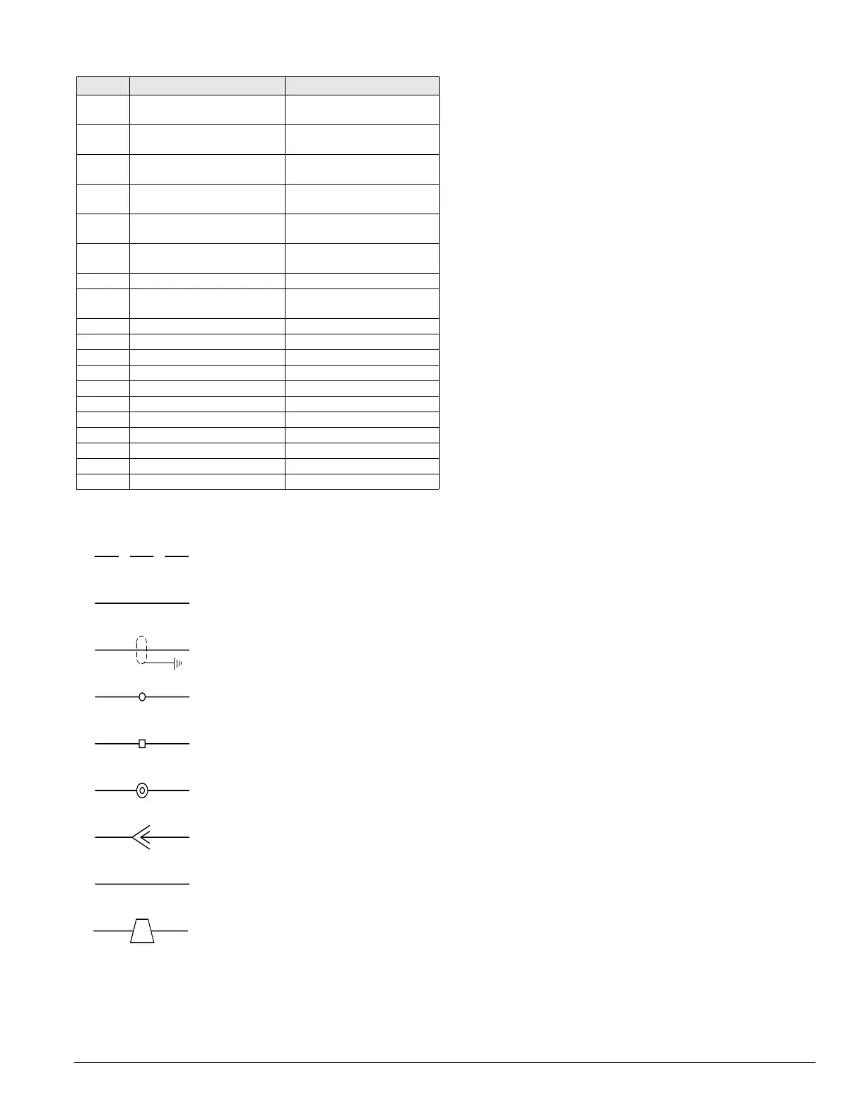
1. Field wiring
3. Shielded wire/cable
4. Main control box
terminals
5. Auxilliary box
terminals
6. Field terminals
7. Plug connector
8. Wire/harness number
General Notes
2. Factory wiring
9. Wire nut/ID
WN7
Daikin IM 696-4 37
Typical Wiring Diagrams
TB23 Terminal block, oil pressure
box, RPE/RCE only
Evap. condenser vestibule
TB25, 26,
27, 28
Terminal block, split unit
junction box
Junction box, split unit
TC12, 13,
14
Temperature controls, Fantrol Condenser section
TC56 Temperature control, water
pipe heater
Evap. condenser vestibule
TC66 Temperature control, vestibule
exhaust fan
Evap. condenser vestibule
TD1, 2 Time delay, compressor
lockout
Main/cond. control box
TD3, 4 Time delay, hi-pressure Main/cond. control box
TD5–8 Time delay, part winding,
compr #1 - 4
Main control box
TD10 Time delay, hi turn down burner Gas heat box
TD11, 12 Time delay, low ambient Main/cond. control box
TR1, 2 Transducer, pressure Main control box
U1, 2 Unloaders, compressors On compressors
UV Ultra-violet light(s) Coil/discharge section
VM1 Valve motor #1, heating Gas heat box/ heat section
VM5 Valve motor #5, cooling Coil section, cool
VV1 Vent valve, gas heat Heat Section, Gas
WL63 Water level, sump, fill Evap. condenser section
WL64 Water level, sump, low water Evap. condenser section
ZNT1 Zone temp. sensor, setback Field installed
ID Description Standard location