EasyManua.ls Logo

Daikin MPS050F User Manual

Daikin MPS050F
132 pages
To Next Page IconTo Next Page
Page #1 background imageLoading...
Page #1 background image
Installation and Maintenance Manual IM 1058-8
Group: Applied Air Systems
Part Number: IM 1058
Date: July 2017
Maverick
®
II
Commercial Packaged Rooftop Systems
Heating and Cooling
Models MPS015F – 0050F
15 to 50 Tons
R-410A Refrigerant
MicroTech
®
III Unit Controller
Energy Recovery Wheel

Table of Contents

Question and Answer IconNeed help?

Do you have a question about the Daikin MPS050F and is the answer not in the manual?

Daikin MPS050F Specifications

General IconGeneral
BrandDaikin
ModelMPS050F
CategoryAir Conditioner
LanguageEnglish

Summary

General Information

Hazard Identification Information

Details dangers, warnings, and cautions for safe operation and handling.

Mechanical Installation

Rigging and Handling

Rigging and Handling

Safety precautions and procedures for lifting and moving the unit using appropriate equipment.

Condensate Drain Pipe Connection

Condensate Drain Pipe Connection

Procedures for properly connecting the condensate drain and installing a P-trap.

Installing Duct Static Pressure Sensor Taps

Electrical Installation

Field Power Wiring

Guidelines for complying with electrical codes and ordinances for power wiring connections.

Preparing Unit for Operation

Optional Gas Heat

Daikin Applied Tubular Heater Series Package Heater Module

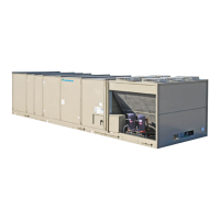
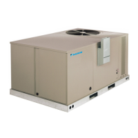
Details on the tubular heater series package for gas heating applications.

Gas Furnace Design and Capacity

Gas Furnace Design

Description of the gas heat furnace design, components, and safety features.

Gas Furnace Safety and Requirements

Gas Furnace Installation Procedures

Installation

Emphasizes professional installation and adherence to codes for the gas furnace.

Gas Piping and Electrical Connections

Gas Pipe Manifold Pressure Adjustment (Natural Gas)

Gas Pipe Manifold Pressure Adjustment for Natural Gas Fuel

Step-by-step guide for adjusting manifold pressure for natural gas furnaces.

Sequence of Operation (Staged Control)

Sequence of Operation (Staged Control)

Details the sequence for low heat (2-stage) and high heat (4-stage) gas furnace operation.

Start-Up Procedures

Start-Up Procedures

Provides instructions for safe and proper start-up of the gas furnace unit.

Ignition Control Module for Staged Gas Furnace

Ignition Control Module for Modulating Gas Furnace

Optional Electric Heat

Electric Heater Design

Overview of the electric heat design, safeties, and capacity options.

Optional Modulating Hot Gas Reheat

Modulating Hot Gas Reheat

Description of the hot gas reheat coil option for dehumidification and temperature control.

Optional Hot Water Heat

Hot Water Heater Design

Information on the hot water coil option, including configuration and piping vestibule.

Optional Energy Recovery Wheel

Energy Recovery Wheel Design

Principles of enthalpy wheel operation for energy recovery and its design considerations.

Optional Outdoor Air Monitor

Thermal Dispersion Airflow Measurement Technology

Explanation of the technology used for measuring airflow and temperature.

Transmitter Troubleshooting

Unit Options

Condenser Fan Operation for Variable Speed Compressor

Condenser Fan Operation for Variable Speed Compressor Low Ambient Option (MPS 040 and 050 Only)

How the VFD controls condenser fan speed for low ambient operation and head pressure control.

VFD Compressor Operation

VFD Compressor Operation

Explanation of VFD compressor operation, modulation, and fixed speed compressor interaction.

VFD Compressor Control

VFD Compressor Control

How VFD compressor control is accomplished via digital output and analog signal.

VFD Compressor Protection

VFD Compressor Protection Unloading Control

Control functions to protect the VFD compressor from damage due to abnormal conditions.

VFD Compressor Protection Features

High Discharge Line Temperature Unloading Control

How high discharge line temperature leads to compressor speed reduction or shutdown.

Low/High Discharge Superheat

Monitoring and control of superheat levels to protect the VFD compressor.

Condenser Coil Splitter and VFD Emergency Stop

VFD Compressor Emergency Stop Control

Functionality and activation of the VFD compressor emergency stop control.

Variable Speed Scroll Compressor

Variable Speed Scroll Compressor

Overview of variable speed scroll compressors, their benefits, and integration.

Oil Injection and Optical Oil Level Sensor

Variable Frequency Drive for VFD Compressor

Variable Frequency Drive for VFD Compressor

Details on the VFD model, its preset parameters, and basic operation for VFD compressors.

Wiring Diagrams

VAV Power – Fixed Speed Scroll Compressor

Electrical schematic showing power wiring for VAV units with fixed speed scroll compressors.

VAV Power with Variable Speed Inverter Compressor

MPS 026 VAV Power with Variable Speed Inverter Compressor

Electrical schematic for MPS 026 VAV units utilizing variable speed inverter compressors.

MPS 030–050 VAV Power with Variable Speed Inverter Compressor

Electrical schematic for MPS 030-050 VAV units with variable speed inverter compressors.

VAV Control – Inputs

VAV Control with Variable Speed Inverter Compressor

VAV Control – without Low Ambient Option

VAV Control – with Low Ambient Option

VAV Control – Outputs (Staged Gas Heat)

Electric Heat Option Power and Outputs

Sequence of Operation

Operating States

Graphical representation of the unit's operating state transitions.

Heating

Control logic for the unit's heating mode based on control temperature and setpoint.

Mechanical Cooling and Economizer

Mechanical Cooling

Operation of the unit in cooling mode, controlled by space or discharge air temperature.

Economizer

Operation of the economizer mode when outside air conditions are favorable for free cooling.

Check, Test, and Start Procedures

Pre-Start of Unit

Essential checks and tests to perform before starting the unit for the first time.

Unit Start-Up Procedures

Compressor Start-Up

Procedures for safely starting compressors, checking refrigerant piping, and fan blade positioning.

Compressor Rotational Direction and Subcooling

Superheat Adjustment and Air Balancing

Expansion Valve Superheat Adjustment

Procedures for adjusting expansion valve superheat for proper compressor efficiency.

Energy Recovery Wheel Checks and Adjustments

Final Control Settings

Controller Settings for Normal Operation

Guide for setting heating, cooling, and other parameters on the MicroTech III controller.

Maintenance Procedures

Performing Service Maintenance

General safety precautions and procedures for performing service maintenance on the unit.

Coil Maintenance

Cleaning Coated Coils

Control Panel Components and Motor Protection

Overload Relays and Circuit Breakers

Energy Recovery Wheel Maintenance

Energy Recovery Wheel Routine Maintenance

Supply Fan and Refrigerant Charge

Refrigerant Charge

Information on proper refrigerant charge and cautions related to pressure switch replacement.

Service and Warranty Procedure

Warranty Registration Form - Electric Heat and Gas Burner Checks

GAS BURNER CHECK, TEST, & START

Specifications and checks for gas burner installation, test, and start-up.

Warranty Registration Form - Gas Burner and Hot Water Coil Checks

GAS BURNER CHECK, TEST, & START (continued)

Continued specifications and checks for gas burner operation and performance.

Related product manuals