Spyder3 GigE Vision User Manual
03-032-20027-02 DALSA
24
!
3.4 Camera Connectors
This camera uses the following connectors:
• An RJ-45 connector for Gigabit Ethernet signals, data signals, and serial
communications. Refer to section Ethernet Connector for details.
• One 6-pin Hirose connector for power. Refer to section Power Connector for details.
• One 15-pin general purpose input/output (GPIO) connector. Refer to section GPIO
Connector for details.
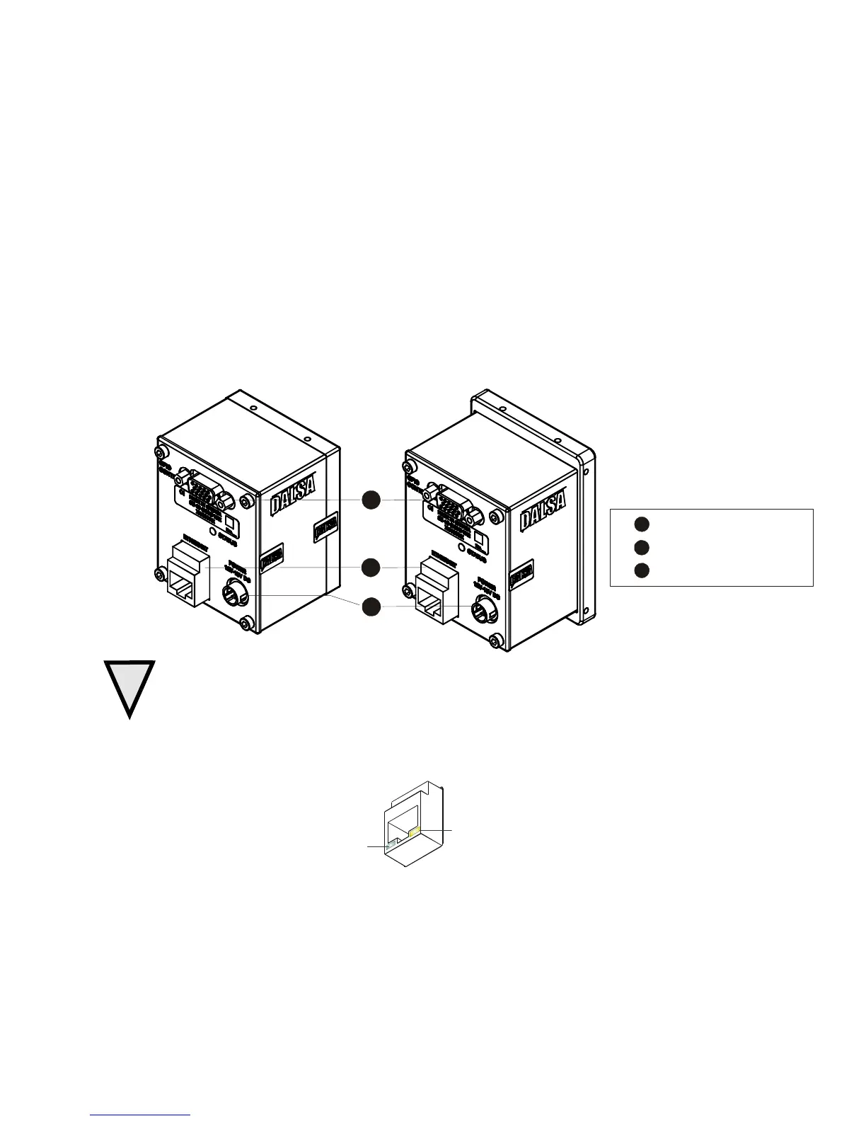
Figure 10: Spyder3 GEV Input and Output Connectors
C
B
A
Ethernet connector
+12V to +15V DC
GPIO connector
C
B
1k and 2k models 4k model
WARNING: It is extremely important that you apply the appropriate voltages to your camera.
Incorrect voltages may damage the camera.
Ethernet Connector
Ethernet Connection
LED@ 1Gbps (Green)
Data Transmission LED
(Yellow)
Ethernet Connection LED
Steady green indicated that an Ethernet connection is successfully established at 1Gbps.
Data Transmission LED
 Loading...


