Spyder3 GigE Vision User Manual
03-032-20027-02 DALSA
26
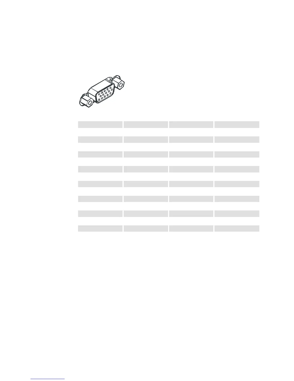
GPIO Connector
The GPIO connector is used to receive or control external signals. For example, the GPIO
connector can be used to receive EXSYNC, PRIN (pixel reset), and direction signals.
Figure 12: GPIO Connector and Pin Numbers
1
5
11
15
Table 5: GPIO Connector Pinout
Pin Signal Description GenICam Default
1
INPUT_ 0+ LVDS/TTL format (positive) EXSYNC +
2
INPUT_0- LVDS (negative) EXSYNC -
3
INPUT_1+ LVDS/TTL format (positive) FrameTrig +
4
INPUT_1- LVDS (negative) FrameTrig -
5
GND
6
INPUT_2+ LVDS/TTL format (positive) Direction +
7
INPUT_2- LVDS (negative) Direction -
8
INPUT_3 TTL auxiliary input
9
OUTPUT_3 TTL auxiliary output
10
OUTPUT_2+ LVDS/TTL auxiliary output
11
OUTPUT_0+ LVDS/TTL auxiliary output
12
OUTPUT_0- LVDS (negative)
13
OUTPUT_1+ LVDS/TTL auxiliary output
14
OUTPUT_1- LVDS (negative)
15
OUTPUT_2- LVDS (negative)
A schematic of the TTL input circuitry is shown in Figure 13: TTL Input Schematic. The
input signals are fed into the engine from external sources via the GPIO connector.
 Loading...


