VLT
®
MICRO
RA
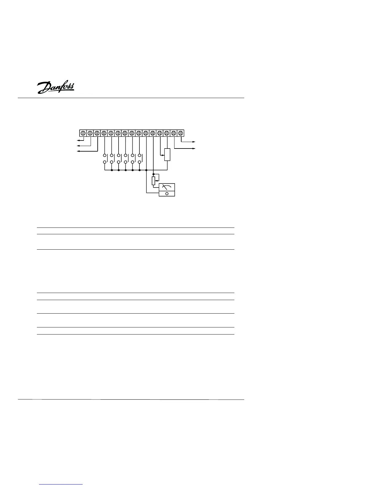
M01MCM+10VAVIAFMGND
M5M4M3M2M1M0RCRB
Relay contactor output
Factory setting:
Forward / Stop
Reverse / Stop
Reset
Multi-step speed 1
Multi-step speed 2
Multi-step speed 3
Photo coupler output
Factory set: Operation
Speed: 3K-5K
Trim potentiometer
VR:1K-5K
Freq. meter
0-10VDC
Full scale voltmeter
Control Terminal Designations
AWG 12-14
Torque 4 kg-cm
Terminal symbol Terminal name Remarks
RA - RC Multi-function output contact Refer to P46,
RB - RC Multi-function output contact Relay Output Contact
M0 - GND Multi-function input 1 Refer to P38, 39, 40, 41, 42
M1 - GND Multi-function input 2
M2 - GND Multi-function input 3
M3 - GND Multi-function input 4
M4 - GND Multi-function input 5
M5 - GND Multi-function input 6
MO1 - MCM Multi-function PHC output 1 Refer to P45
+10V - GND Power supply for speed control Command for power supply
(+10 V)
AVI - GND Analog voltage freq. command 0 - 10V or 4 - 20mA
inputs (10V and 20mA = max. freq.)
AFM - GND Analog frequency/current meter 0 - 10 V output ( 10 V = max. freq.)
Note : Use twisted-shielded or twisted-pair shielded wires for the control signals. It is
recommended to run all signal wiring in a separate steel conduit. The shield wire should
only be connected to ground at the drive end of the cable.
11