Do you have a question about the Danfoss 176F7302 and is the answer not in the manual?
Guide to initial setup, unpacking, and basic operation of the drive.
Guidelines for physically installing the drive, including ventilation and space requirements.
Instructions for connecting the drive's main and control circuits.
Important considerations for proper installation of the drive.
A simplified procedure for initial drive configuration and setup.
Selects the source for master frequency control.
Determines how the drive receives operation commands.
Configures how the motor stops when a stop command is received.
Defines the Voltage/Frequency curve for motor control.
Sets acceleration and deceleration times for motor control.
Sets acceleration/deceleration time for jog operations.
Defines the frequency for jog operations.
Configures multiple speed settings for operation.
Prevents stalling due to over-voltage during deceleration.
Configures parameters to prevent stalling due to over-current.
Sets upper and lower limits for the reference frequency.
Selects analog output signal (frequency or current).
Adjusts the level of the analog output signal.
Sets the motor's rated current for protection.
Configures electronic thermal overload protection for the motor.
Sets how over-torque detection operates.
Stores and displays the three most recent fault records.
Controls the execution mode of the PLC program.
Controls the direction of motion for multi-speed parameters.
Sets the motor's rated current for protection.
Configures electronic thermal overload protection for the motor.
Stores and displays the three most recent fault records.
Controls the execution mode of the PLC program.
Categorizes different types of AC motor drive failures.
Lists common faults and their corresponding solutions for troubleshooting.
| Type | Controller |
|---|---|
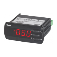
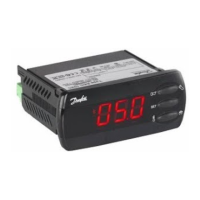
| Model Number | 176F7302 |
| Brand | Danfoss |
| Supply Voltage | 24 V AC/DC |
| Digital Inputs | 4 |
| Relay Outputs | 2 |
| Analog Inputs | 2 |
| Output Current | 5 A |
| Protection Class | IP20 |
| Communication Protocol | Modbus RTU |
| Communication | RS485 |
| Operating Temperature | -10°C to +55°C |