VLT
®
MICRO
12.d18: Counter Trigger – Parameter value d18 programs a Multi-function Input
Terminal: M1 (Pr.38), M2 (Pr.39), M3 (Pr.40), M4 (Pr.41) or M5 (Pr.42) to increment the
AC drive's internal counter. When the input transitions from low to high the counter is
incremented by 1.
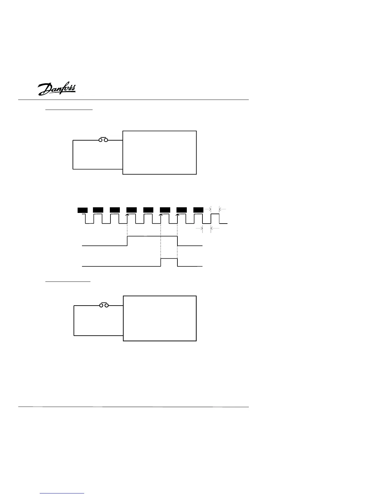
Application Note:
The Counter Trigger input can be connected to an external sensor to count a process
step or unit of material used in a process. Refer to the diagram below.
13.
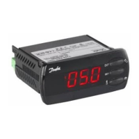
d19: Counter Reset – Parameter value d19 programs a Multi-function Input
Terminal: M1 (Pr.38), M2 (Pr.39), M3 (Pr.40), M4 (Pr.41) or M5 (Pr.42) to reset the
counter.
Application Note:
The input terminal resets the counter to "00" which can be displayed on the Digital
Keypad/Display.
GND
Mx Counter value add. one unit by
signal "On" to "Off".
Trigger
d18 Counter trigger
signal input.
VLT MICRO
Mx "Closed": Operation available.
Indicated by c00 on display.
GND
Reset Counter
d19 Reset the counter
value.
VLT MICRO
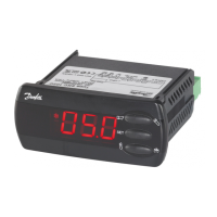
Counter trigger signal
Indication Value
(P64)
Multi-function input terminal
Signal output with (P96 = d05)
Pr.-96 counter (P45/P46)
value is attained.
Signal output with (P97 = d03)
Pr.-97 counter (P45/P46)
value is attained.
2mS
2mS
The trigger timing can not be
less than 2mSec. (<250Hz)
c 02
c 03
c 02
c 01
c 00
c 01c 05c 04
39