VLT
®
MICRO
Chapter 3
Digital Keypad/Display Operation
Chapter 3 describes the various controls and indicators found on the Digital Keypad/
Display. The information in this chapter should be read and understood before
performing the start-up procedures described in Chapter 4.
• Description of the Digital Keypad/Display
• Description of Display
• Digital Keypad Operating Modes & Programming Steps
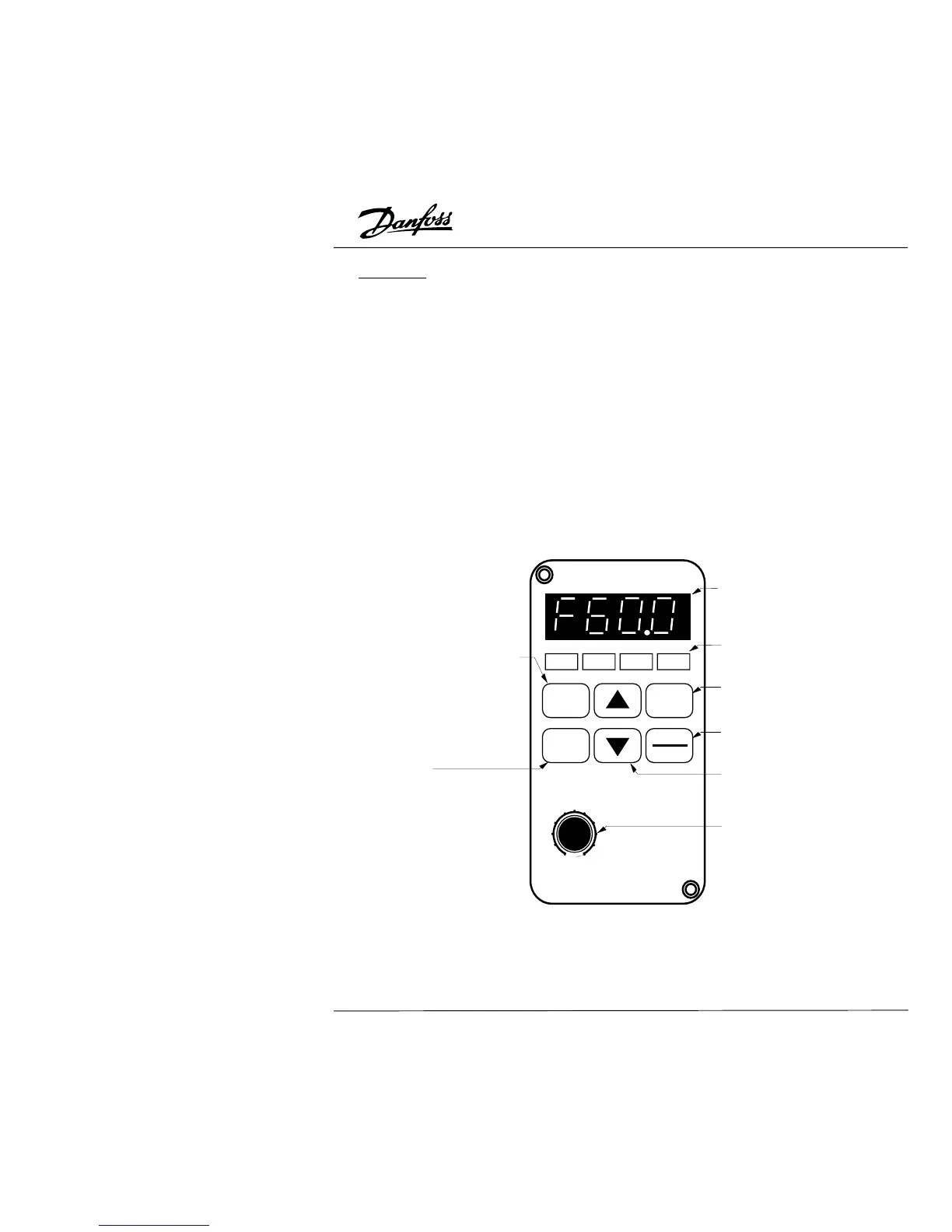
Description of the Digital Keypad/Display
Operating Modes and Functions
When delivered from the factory, the Digital Keypad/Display module is mounted on the
front panel of the AC drive. This module has two functions: display and control. The
Display shows the current status of the drive. The control function provides the
programming interface.
RUN
STOP
FWD
REV
MODE
RUN
ENTER
STOP
RESET
FREQ SET
50
100
0
LED Display
Indicates frequency, motor
parameter setting value and
alarm contents.
Program / Function Data Key
Selects normal mode / program mode.
Displays the motor drive status, such
as output freq., selects the parameters,
FWD/REV or output current, etc.
ENTER Key
Sets the different parameters
LED Indication
Lamp lights during RUN,
STOP, FWD & REV operation.
RUN Key
Starts inverter drive operation.
STOP/RESET Key
Stops and resets the parameter
after faults occur.
UP and DOWN Key
Sets the parameter number or
changes the numerical data
such as the freq. reference.
VR for Setting Freq.
Could be the main-freq. input by
setting parameter Pr.00.
14