VLT
®
MICRO
Chapter 4
Description of Parameters
Pr.00 Master Frequency Source Select
Factory Setting d00
Units None
Settings d00 Master frequency determined by keypad digital control.
d01 Master frequency determined by analog signal of DC 0V - +10V,
a. Performed by keypad potentiometer. The pin header and jumper
combined as 1 and 3 in the diagram below.
b. Performed by external terminal AVI. The pin header and jumper
combined as 2 and 3 in the diagram below.
d02 Master frequency determined by analog signal of DC 4mA - 20mA.
Performed by external terminal AVI. The pin header and jumper
combined as 2 and 4 in the diagram below.
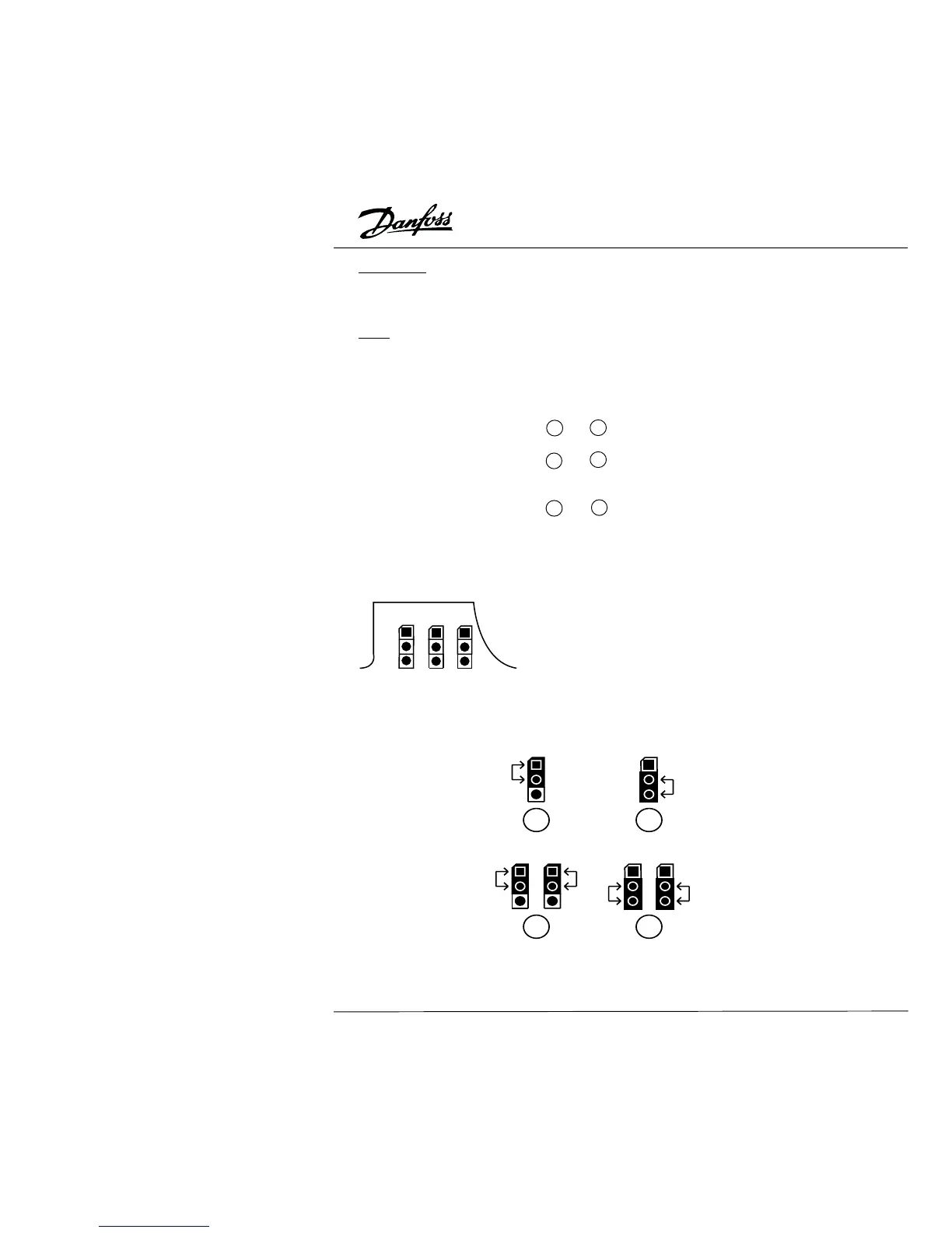
Pin Header/Jumper Diagrams:
The pin headers and jumpers are located on the upper right corner of the control board
and can be accessed by opening the input terminal cover.
J5: Selects the source of the potentiometer input from
the External Control Terminal (AVI) or from the
Digital Keypad/Display (LC-03P) potentiometer.
J6, J7: This jumper is used to select the DC voltage signal
or DC current signal for master frequency control.
J5 J6 J7
1
2
3