VLT
®
MICRO
In the following examples the output frequency and direction of motion is controlled by a
potentiometer connected to the external terminals or the potentiometer in the Digital
Keypad/Display. Observe the interaction and effect of parameters: Pr.48, 49, 50, 51 on
the potentiometer operation.
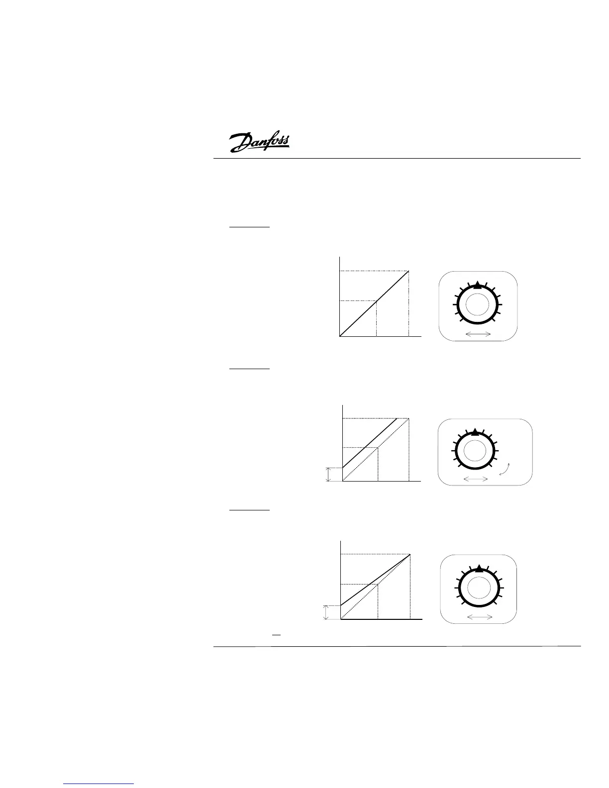
Example 1: The configuration in this example is the most common. Set Pr.00 to d00,
d01 or d02 and select J5, J6, J7 jumper settings to control the output frequency:
through potentiometer in the Digital Keypad/Display, or through the external AV1: 0-10 V,
4-20 mA.
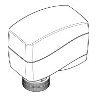
Example 2: In this example the output frequency range is 10 Hz to 60 Hz. Turning the
potentiometer fully counter clockwise, corresponds to an output frequency of 10 Hz.
Turning the potentiometer fully clockwise, to the stop, corresponds to 60 Hz. The
midpoint corresponds to 40 Hz. The effective AVI signals are: 0-8.33 V or 4-13.33 mA.
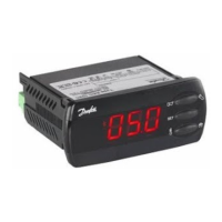
Example 3: In this example the Process Signal Gain (Pr.50) is d83%. The control range
of the potentiometer is 10 - 60 hz as shown below. The corresponding range on the
external AVI terminals is: 0-10 V and 4-20 mA.