Displacement Limiters
D1P displacement limiter screws removal
The removal steps of the maximum (bottom of the pump) and minimum (top of the pump, control side)
are the same.
1. Loosen the lock nut (F120) with an external hex wrench.
2. Counter clockwise turn the adjusting screw (F110) with an 8mm internal hex wrench until it
completely out.
3. Inspect the lock nut seal and adjusting screw, if they are damaged , discard them.
D1P displacement limiter screws installation
The installation steps of the maximum (bottom of the pump) and minimum (top of the pump) are the
same.
1. Clockwise turn the adjusting screw (F110) with the appropriate internal hex wrench until you feel it
start against the swashplate.
2. Install the lock nut (F120), while holding the adjusting screw position, torque the lock nut to required
torque.
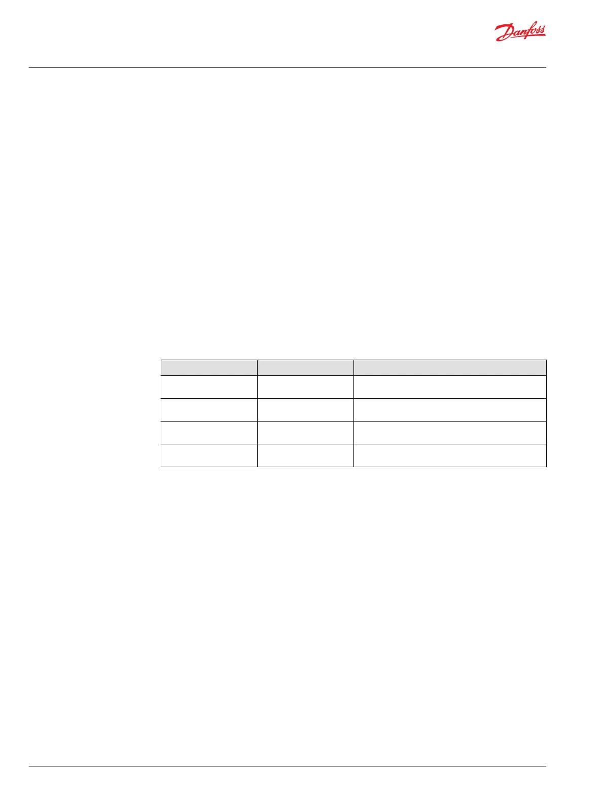
Wrench size and torque
Frame size Wrench size Torque
65cc 5 mm (screws), 17 mm
(nuts)
43~48 N·m [380.58~424.84 lbf·in]
130/145cc 5 mm (screws) 17 mm
(nuts)
43~48 N·m [380.58~424.84 lbf·in]
193cc 8 mm (screws), 24 mm
(nuts)
180~206 N·m [1593.13~1823.25 lbf·in]
260cc 8 mm (screws), 24 mm
(nuts)
180~206 N·m [1593.13~1823.25 lbf·in]
Service Manual
D1 High Power Open Circuit Pumps Size 65/130/145/193/260
Minor repairs
54 |
©
Danfoss | July 2019 L1527453 | AX00000292en-CN0201