Application 10
EI.65.D4.02
80
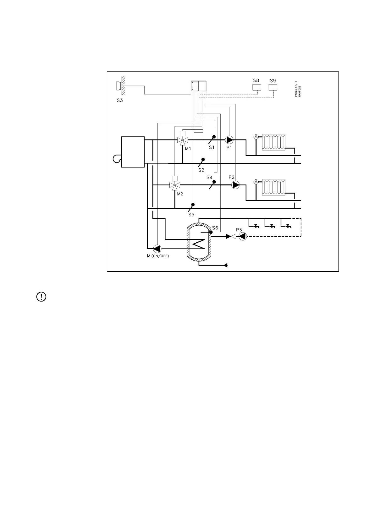
System diagram 10B
Boiler system with control of two heat circuits and a hot-water tank
Note:
This application is designed for ECL 2000 Type 1 and is not used with Type 2.
Heat circuit 1 The heat circuit is connected directly to the boiler. The mixing valve M1 controls
the flow temperature, which is measured by the sensor S1. The return temperature
measured by the sensor S2 can be limited. The circulation pump P1 is running
when the reference flow temperature is above 20 °C or the outdoor temperature is
below 2 °C.
Heat circuit 2 The heat circuit is connected directly to the boiler. The mixing valve M2 controls
the flow temperature, which is measured by the sensor S4. The return temperature
measured by the sensor S5 can be limited. The circulation pump P2 is running
when the reference flow temperature is above 20 °C or the outdoor temperature is
below 2 °C.
Hot-water circuit The charging pump M
(ON/OFF)
performs on/off control of the storage tank tempera-
ture, which is measured by the sensor S6. The circulation pump P3 is not con-
trolled by the ECL 2000.