1.
2.
3.
4.
5.
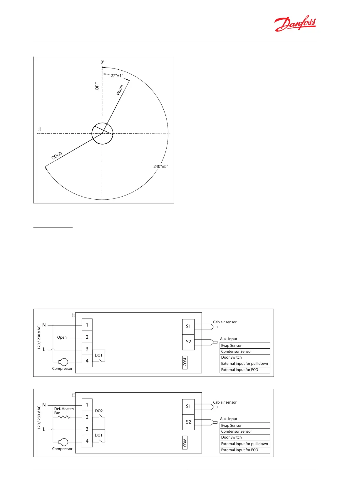
Figure 16: EETc11, EETc12
Evap Sensor
1
2
S1
S2
3
N
L
4
DO1
Aux. Input
Cab air sensor
Compressor
120 / 230 V AC
COM
Open
Condensor Sensor
Door Switch
External input for pull down
External input for ECO
Danfoss
80G404
Figure 15: Operation (Spindle operation) for EETc and EETa
240°±5°
27°±1°
OFF
Warm
COLD
0°
Danfoss
80G403
Spindle shown in "Warm" position.
Connections
WARNING:
Do not t power supply wiring and signal wiring (probes/sensors and digital inputs) in the same raceways or
ducts.
Separate as much as possible the probe and digital input signal cables from the cables carrying inductive loads
and power cables to avoid possible electromagnetic disturbance.
Suitably fasten the output connection cables to avoid any unintentional contact.
The electrical connections must only be completed by a qualied electrician.
The customer must only use the product in the manner described in the documentation relating to the
installation and product application.
Figure 17: EETc21, EETc22
Evap Sensor
1
2
S1
S2
3
N
L
4
DO1
Aux. Input
Cab air sensor
Compressor
120 / 230 V AC
COM
Condensor Sensor
Door Switch
External input for pull down
External input for ECO
Danfoss
80G405
DO2
Def. Heater/
Fan
© Danfoss | Climate Solutions | 2023.07 BC320944106159en-000301 | 11
Refrigeration controller, type EET series