1.
2.
3.
Troubleshooting and Alarms
Troubleshooting
Table 26: Troubleshooting
Compressor does not start
Spindle is in “OFF” position
Waiting for power on delay
Cabinet air temperature is less than compressor cut-in temp.
Defrost is in progress
Line voltage is too low or too high
High condenser temperature
Change spindle position by rotating clockwise.
Check and wait untill “Pod” expiries.
Check cabinet air sensor temp. “att”
Check and wait untill dAt and dot expires.
Check line voltages are within low and high voltage limits speci-
ed under uLi, uLo and uHo.
Check for condenser sensor temp’ct1’ and congured condenser
block limit’cbL’.
Door is open or door contact is defective
Check “Fdt” and door status. Check that door contact is ok
Fan stopped due to high evaporator temp.
Check evaporator sensor temp. “Et1/Et2” and FLt.
Fan start delay and temp. after defrost
Check for ‘Fdd’ and “Ftd” parameters’ conguration
Controller in Initial Pull Down or Pull-down mode
Defrost is skipped during pull-down. Check the thermostat sta-
tus and congured pull-down duration.
Check alarm delay for temperature ‘Ltd /Htd’ and door ‘dod’
Does not maintain correct cabi-
net temperature
Check the S1 sensor and sensor alarm status
Check the controller potentimeter function
Frost is not fully melted during
defrost
Evaporator sensor position not proper Too long defrost intervals
Congured defrost time is too short
Check the position and tting of the evaporator sensor
Check for congured dii, dAi, dit and dAt values
Alarms
Alarms (advanced version only) Indication
The EET controller indicates the fault or failure in the refrigeration system via an LED ashing pattern, sending a
message via MODBUS to KoolProg or any other tools. Below the LED blinking pattern for various alarms are stated:
Table 27: Alarms
Low and High temperature alarm
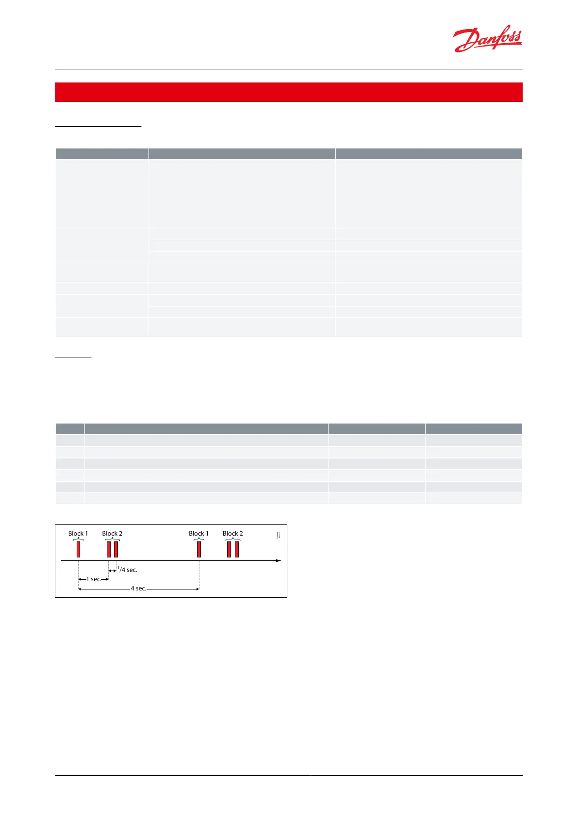
Figure 26: Indication of Line Voltage Alarm
Danfoss
80G415
4 sec.
1 sec.
¹/4 sec.
Block 1 Block 2 Block 1 Block 2
NOTE:
LED blinking every one second indicates power ON status and no alarm conditions.
Alarms to be interpreted as per block1 and block 2 blinking pattern as given in the table. After block 1 and Block
2 blinking there is about 2.5 seconds gap.
If there are multiple alarms, LED blinking pattern shows the alarm raised rst, next active alarm will be displayed
only when the rst raised alarm is xed.
Refrigeration controller, type EET series
© Danfoss | Climate Solutions | 2023.07 BC320944106159en-000301 | 28