FC 300 Profibus
How to Install
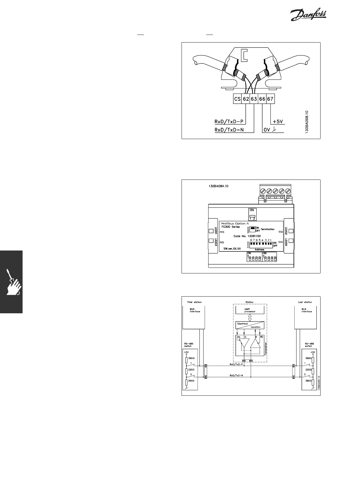
Connecting the Bus Line
Proper termination of the bus line is essential. A
mismatch of impedance may result in reflections on
the line that will corrupt data transmission.
- The PROFIBUS Option Card has a suitable
termination, activated by switch 1 located on
the Profibus option. The switches must be on to
terminate the bus. The factory setting is off.
- Nodes at the physical ends of each segment
must be terminated.
- When power to the PROFIBUS card is down,
please note t hat the termination is still active,
although not functional.
- Most masters and repeaters are equipped with
their own termination.
- If an external termination circuit consisting of
three resistors is connected to the bus line, a
5V DC power supply must be used. Please note
that this power supply must be galvanically
isolated from the a.c. line.
62 = RxD/TxD-P red cable (Siemens B)
63 = R xD /TxD-N green cable (Siemens A)
16
MG.33.C2.02 - VLT is a registered Danfoss trademark