FC 300 Profibus
How to Control the FC 300
Control P rofile
The FC 300 can be controlled according to the PROFIdrive profile, or the Danfoss FC profile. Select the desired
control profile in par. 8-10 Control word profile. The c hoice of profile affects the control and status word only.
The PROF Idrive control profile and Danfoss FC control profile sections provide a detailed description of
control and status data.
PROFIdrive Control Profile
This section describes the f unctionality of the control word and status word in the PROFIdrive profile. Select
this profile by setting par. 8-10 Control word profile to PROFIdrive.
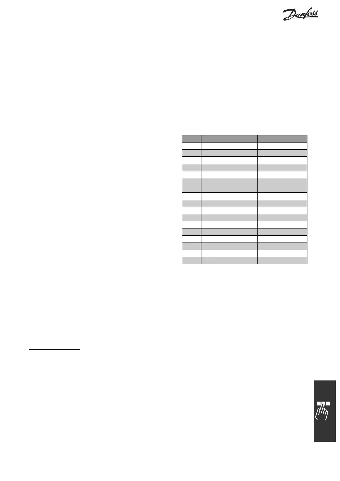
Control Word according to PROFIdrive Profile
(CTW)
The Control word is used to send commands from
amaster(e.g. aPC)toaslave.
Bit Bit = 0 Bit = 1
00 OFF 1 ON 1
01 OFF 2 ON 2
02 OFF 3 ON 3
03 Coasting No coasting
04 Quick stop Ramp
05 Hold fre quency
output
Use ramp
06 Ramp stop Start
07 No function Reset
08 Jog 1 OFF Jog 1 ON
09 Jog 2 OFF Jog 2 ON
10 Data invalid Data valid
11 No function Slow do wn
12 No function Catch up
13 Parameter set-up Selection lsb
14 Parameter set-up Selection msb
15 No function Reverse
Explanation of the Control Bits
B
it 00, OFF 1/ON 1
Normal ramp stop using the ramp times of the actual selected ramp.
Bit 00 = "0" leads to the stop and activation of the output relay 1 or 2 if the output frequency is 0 Hz and if
[Relay 123] has been selected in par. 5-40 Function relay.
When bit 00 = "1", the frequency converter is in State 1: “Switching on inhibited”.
Please refer to the PROFIdrive State Transition Diagram, at the end of this section.
B
it 01, OFF 2/ON 2
Coasting stop
When bit 01 = "0", a coasting stop and activation of the output relay 1 or 2 occurs if the output frequency is
0 Hz and if [Relay 123] has been selected in par. 5-40 Function relay.
When bit 01 = "1", the frequency converter is in State 1: “Switching on inhibited”. Please refer to the
PROFIdrive State Transition Diagram, at the end of this section.
B
it 02, OFF 3/ON 3
Quick stop using the ramp time of par. 3-81 Quick stop ramp time. When bit 02 = "0", a quick stop and
activation of the output relay 1 or 2 occurs if the output frequency is 0 Hz and if [Relay 123] has been
selected in par. 5-40 Function relay.
When bit 02 = "1", the frequency converter is in State 1: “Switching on inhibited”.
Please refer to the PROFIdrive State Transition Diagram, at the end of this section.
29
MG.33.C2.02 - VLT is a registered Danfoss trademark