Operating variable: Unit:
16-00 Control Word hex
16-01 Reference [Unit] [unit]
16-02 Reference % %
16-03 Status Word hex
16-05 Main Actual Value [%] %
16-10 Power [kW] [kW]
16-11 Power [hp] [HP]
16-12 Motor voltage [V]
16-13 Frequency [Hz]
16-14 Motor Current [A]
16-16 Torque [Nm] Nm
16-17 Speed [RPM] [RPM]
16-18 Motor Thermal %
16-20 Motor Angle
16-30 DC Link Voltage V
16-32 Brake Energy /s kW
16-33 Brake Energy /2 min kW
16-34 Heatsink Temp. C
16-35 Inverter Thermal %
16-36 Inv. Nom. Current A
16-37 Inv. Max. Current A
16-38 SL Controller State
16-39 Control Card Temp. C
16-40 Logging Buffer Full
16-50 External Reference
16-51 Pulse Reference
16-52 Feedback [Unit] [Unit]
16-53 Digi Pot Reference
16-60 Digital Input bin
16-61 Terminal 53 Switch Setting V
16-62 Analog Input 53
16-63 Terminal 54 Switch Setting V
16-64 Analog Input 54
16-65 Analog Output 42 [mA] [mA]
16-66 Digital Output [bin] [bin]
16-67 Pulse Input #29 [Hz] [Hz]
16-68 Freq. Input #33 [Hz] [Hz]
16-69 Pulse Output #27 [Hz] [Hz]
16-70 Pulse Output #29 [Hz] [Hz]
16-71 Relay Output [bin]
16-72 Counter A
16-73 Counter B
16-80 Fieldbus CTW 1 hex
16-82 Fieldbus REF 1 hex
16-84 Comm. Option Status hex
16-85 FC Port CTW 1 hex
16-86 FC Port REF 1 hex
16-90 Alarm Word
16-92 Warning Word
16-94 Ext. Status Word
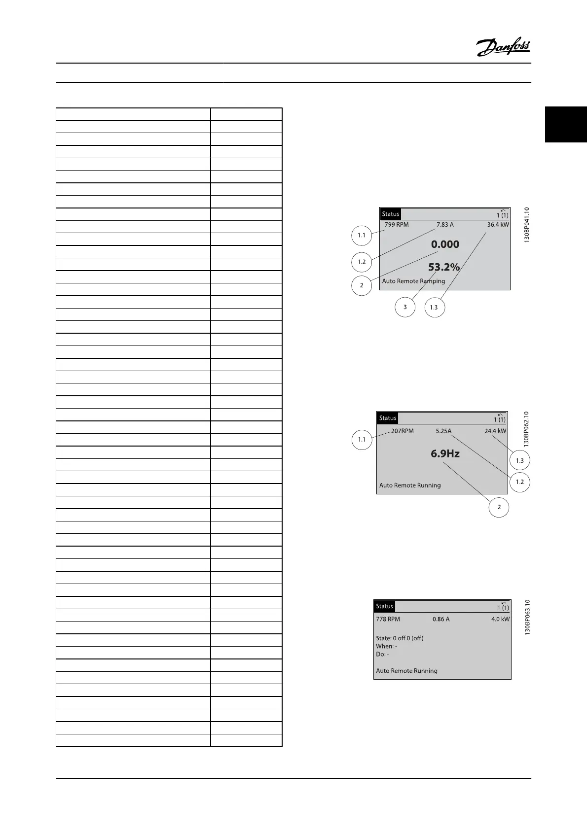
Status screen I:
This readout state is standard after start-up or initialization.
Use [INFO] to obtain information about the measurement
links to the displayed operating variables (1.1, 1.2, 1.3, 2 and
3).
See the operating variables shown on the screen in this
figure.
Status screen II:
See the operating variables (1.1, 1.2, 1.3 and 2) shown on the
screen in this figure.
In the example, Speed, Motor current, Motor power and
Frequency are selected as variables in the first and second.
Status screen III:
This state displays the event and action of the Smart Logic
Control. For further information, see section Smart Logic
Control.
How to Program FC 300 Programming Guide
MG.33.MA.22 - VLT
®
is a registered Danfoss trademark 2-5
2

 Loading...


