4Spare Parts
4.1.1 Spare Parts
NB!
Unless otherwise indicated, spare part kits contain only one of each item.
All images in this section are indicative.
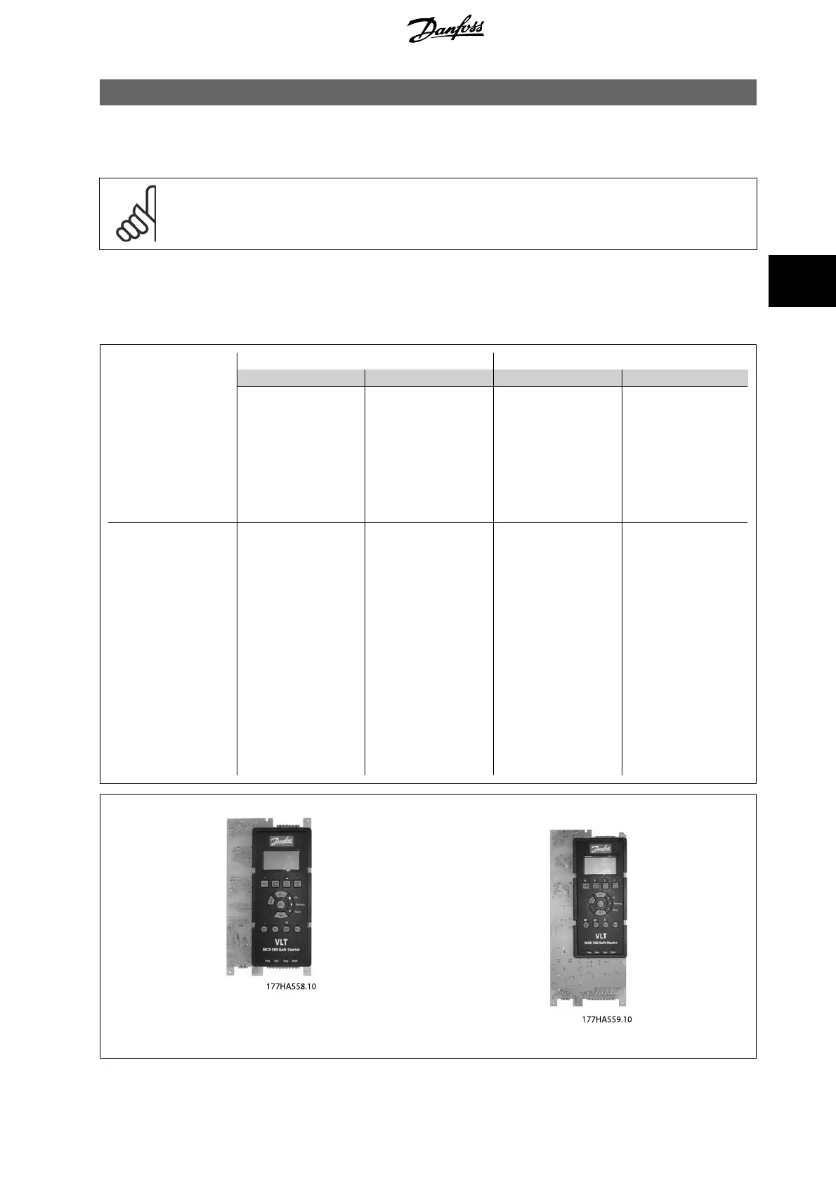
4.2 Main Control PCB
Each soft starter requires one Main Control PCB.
CV1
CV3
T5 T7 T5 T7
MCD5-0021B
175G5603 175G5604 175G5601 175G5602
MCD5-0037B
MCD5-0043B
MCD5-0053B
MCD5-0068B
MCD5-0084B
MCD5-0089B
MCD5-0105B
MCD5-0131B
175G5607 175G5608 175G5605 175G5606
MCD5-0141B
MCD5-0195B
MCD5-0215B
MCD5-0241C
MCD5-0360C
MCD5-0380C
MCD5-0428C
MCD5-0595C
MCD5-0619C
MCD5-0790C
MCD5-0927C
MCD5-1200C
MCD5-1410C
MCD5-1600C
175G5601 - 175G5604 175G5605 - 175G5608
MCD 500 Service Manual 4 Spare Parts
MG.17.L1.02 - VLT
®
is a registered Danfoss trademark
21
4